1. Introduction
The Ardest HW632 is an automatic battery charging control module designed to manage the charging process for 12V-24V lead-acid and lithium-ion batteries. This module features real-time voltage monitoring, automatic charge initiation and termination, and user-configurable voltage settings to prevent overcharging and prolong battery life. It is suitable for various applications, including solar power systems, automotive, and general battery charging setups.

Figure 1: Ardest HW632 Battery Charging Control Module. This image displays the top view of the blue circuit board with its components, including the 3-digit LED display, control buttons, and terminal blocks.
2. Product Features
- Automatic control circuit connection for simplified setup.
- Automatic charging and power-off functionality to prevent overcharging.
- Real-time voltage monitoring via a 3-digit red LED display.
- Auto-save setting feature retains user configurations.
- Utilizes an ST core chip for reliable performance.
- Integrated LM2596 switch voltage regulator.
- User-configurable start and stop charging voltages.
- On-board momentary push buttons for easy voltage setting.
- Module disconnects power supply to prevent battery overcharging.
- Compatible with lead-acid batteries, lithium-ion batteries, nickel-cadmium batteries, nickel-metal hydride batteries, polymer batteries, car batteries, and electric car batteries.
- Suitable for use with solar panels.
3. Specifications
| Parameter | Value |
|---|---|
| Model | HW632 |
| Input Voltage | DC 10-30V |
| Rated Current | 20A |
| Display Precision | 0.1V |
| Control Precision | 0.1V |
| Output Type | Direct Output |
| Voltage Tolerance | +/-0.1V |
| Application Fields | 12-24V Storage Battery |
| Dimensions (L x W x H) | 82mm x 58mm x 18mm (3.23 x 2.28 x 0.71 inches) |
| Item Weight | 1.58 ounces |

Figure 2: Dimensions of the Ardest HW632 module. The image shows the module with measurements indicating a length of 82mm, width of 58mm, and height of 18mm.
4. Setup and Wiring
Proper connection of the HW632 module is crucial for safe and effective operation. Ensure all connections are secure before applying power.
4.1 Component Identification

Figure 3: Labeled components of the Ardest HW632 module. This image highlights the voltage display digital tube, the 'Start' voltage setting button, the 'Stop' voltage setting button, and the output indicator LED.
4.2 Wiring Diagram
Connect the charger input and battery detection port to the module as shown in the diagram below. The module requires a DC 10-30V input from your charger. The battery to be charged should be a 12V-24V storage battery.

Figure 4: Wiring diagram for the Ardest HW632 module. This diagram illustrates how to connect a charger input and a 12-24V storage battery to the module's terminal blocks.
4.3 Solar Panel Integration
The HW632 module can also be integrated into a solar charging system. Connect the solar panel output to the module's input, and the module's output to the battery.
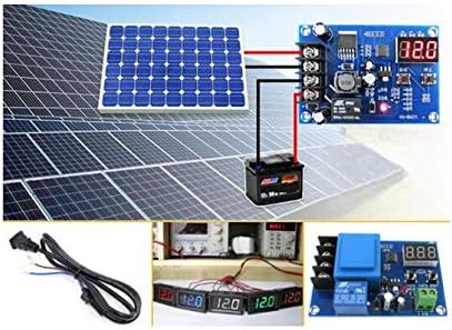
Figure 5: Solar panel connection diagram. This image shows the HW632 module connected between a solar panel array and a battery, demonstrating its use in a solar charging setup.
5. Operating Instructions
The module features two push buttons for setting the charging parameters and a 3-digit LED display for real-time voltage monitoring.

Figure 6: Diagram illustrating the 'Using Method' for the Ardest HW632 module, showing the start and stop buttons and their functions for setting voltage and resetting.
5.1 Setting the Start Charging Voltage
- In the normal voltage display state, press the Start button once. The display will show the current start charging voltage.
- Long press the Start button for approximately 3 seconds. The digital display will begin to flash.
- While the display is flashing, use the Start button to increase the voltage value and the Stop button to decrease the voltage value.
- Once the desired start charging voltage is set, wait for a few seconds without pressing any buttons. The module will automatically save the setting and return to the normal voltage display.
5.2 Setting the Stop Charging Voltage
- In the normal voltage display state, press the Stop button once. The display will show the current stop charging voltage.
- Long press the Stop button for approximately 3 seconds. The digital display will begin to flash.
- While the display is flashing, use the Start button to increase the voltage value and the Stop button to decrease the voltage value.
- Once the desired stop charging voltage is set, wait for a few seconds without pressing any buttons. The module will automatically save the setting and return to the normal voltage display.
5.3 Factory Reset
To restore the module to its factory default settings:
- Ensure the module is powered on.
- Simultaneously press and hold both the Start and Stop buttons.
- The digital display will show "888", indicating that the factory reset has been performed successfully.
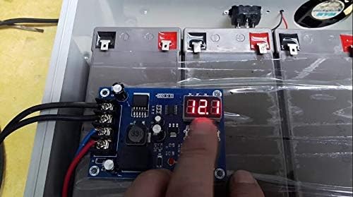
Figure 7: A user's hand interacting with the Ardest HW632 module, demonstrating the process of pressing the control buttons to adjust settings.
6. Maintenance
The Ardest HW632 module is designed for low maintenance. However, periodic checks can ensure optimal performance and longevity:
- Cleanliness: Keep the module free from dust, dirt, and moisture. Use a soft, dry cloth for cleaning.
- Connections: Periodically inspect all wiring connections to ensure they are tight and free from corrosion. Loose connections can lead to inefficient operation or damage.
- Environment: Operate the module within its specified temperature and humidity ranges. Avoid exposing it to extreme conditions.
7. Troubleshooting
If you encounter issues with your Ardest HW632 module, consider the following troubleshooting steps:
- No Display/No Power:
- Ensure the input voltage is within the DC 10-30V range.
- Check all power connections for proper polarity and secure contact.
- Verify that the battery is connected, as the module may not display without a battery connected.
- Battery Not Charging:
- Confirm that the start charging voltage is set below the current battery voltage.
- Check the charger's output to ensure it is providing power.
- Inspect all wiring for breaks or loose connections.
- Battery Overcharging:
- Verify that the stop charging voltage is set correctly for your battery type.
- Perform a factory reset (refer to Section 5.3) and reconfigure the voltage settings.
- Incorrect Voltage Readings:
- Ensure connections are clean and secure to avoid voltage drops.
- Compare readings with a calibrated multimeter if possible.
8. Safety Information
Please observe the following safety precautions when installing and operating the Ardest HW632 module:
- Always disconnect power before making or changing any wiring connections.
- Ensure correct polarity when connecting the input power and battery. Incorrect polarity can damage the module and connected devices.
- Do not exceed the maximum rated current of 20A.
- Operate the module in a well-ventilated area to prevent overheating.
- Keep the module away from water, flammable materials, and corrosive substances.
- This module is not a toy. Keep out of reach of children.
- If you are unsure about any installation or operation steps, consult a qualified technician.
9. Warranty and Support
The Ardest HW632 Battery Charging Control Module is manufactured by Ardest. For specific warranty information or technical support, please refer to the documentation provided with your purchase or contact your retailer. General inquiries can be directed to the manufacturer via their official support channels.