
Introduction
This manual provides detailed instructions for the installation, operation, and maintenance of the SENRISE TB6560 3A Driver Board. This driver board is designed for controlling two-phase, four-phase, four-wire, or six-wire stepper motors with a current rating up to 3A. It features advanced control capabilities and protection circuits to ensure reliable performance.
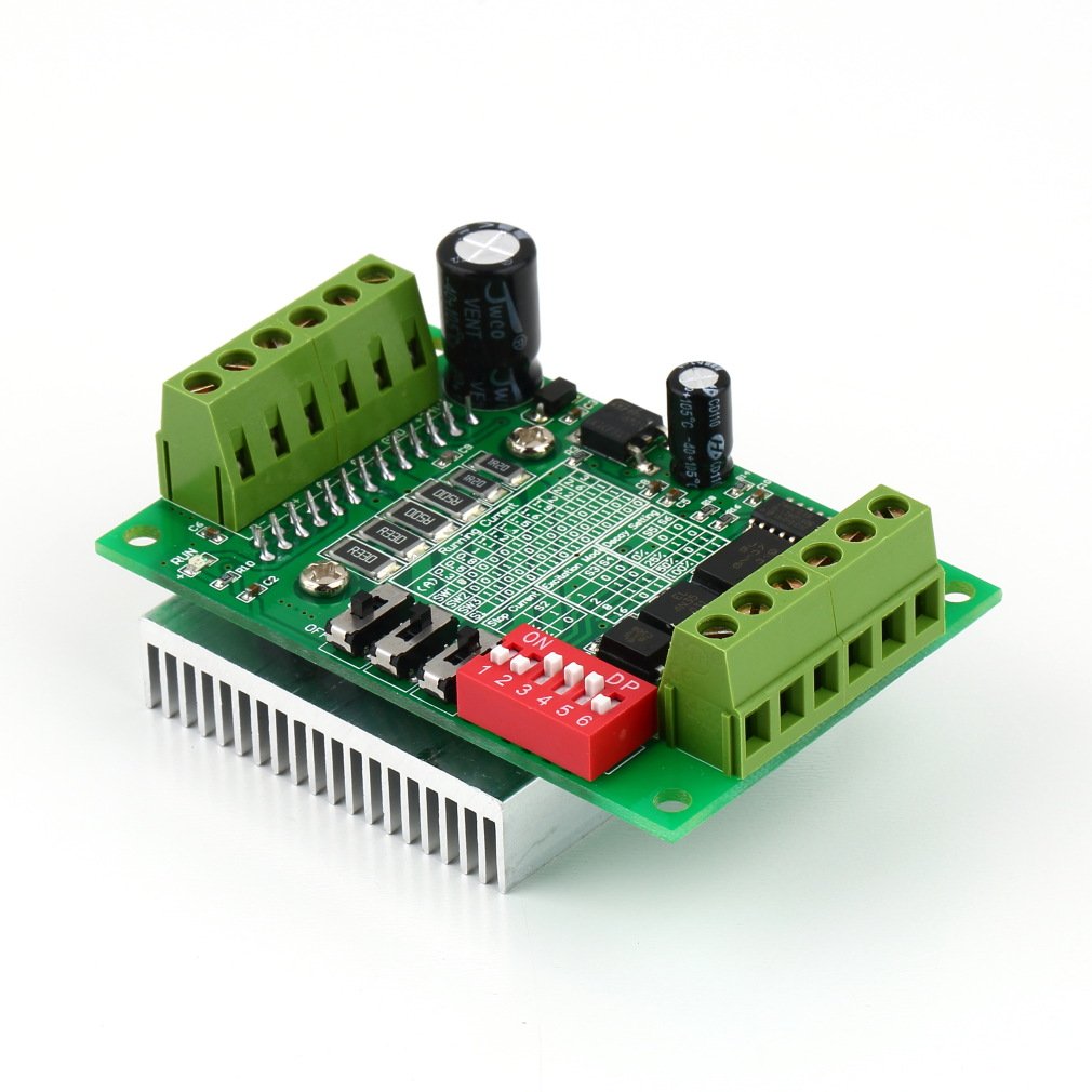
Image: Overall view of the SENRISE TB6560 3A Driver Board. This image provides a general perspective of the product, including its main components and compact form factor.
Key Features
- Adjustable Current Level: The output current can be precisely adjusted to match various application requirements.
- Automatic Semi-Flow Function: Enhances motor efficiency and reduces heat generation during idle states.
- High-Speed Optocoupler Isolation: Utilizes 6N137 high-speed optocouplers to ensure high-speed operation without losing steps.
- Integrated Protection Circuits: Features low voltage shutdown, overheat shutdown, and overcurrent protection for enhanced reliability and longevity of the Toshiba TB6560AHQ chip.
- Wide Voltage Range: Operates with a DC input voltage of 10V-35V, with DC24V recommended for optimal performance.
- Micro-Stepping Capabilities: Supports full step, half step, 1/8 step, and 1/16 step subdivisions, allowing for smoother motor movement.
- Compact Design: Dimensions of 50mm (width) × 75mm (length) × 35mm (height) for easy integration.
- Effective Heat Dissipation: Equipped with a thick-toothed radiator for efficient cooling.
Technical Specifications
| Parameter | Value |
|---|---|
| Working Voltage | DC 10V-35V (Recommended DC24V) |
| Chipset | Toshiba TB6560AHQ |
| Rated Maximum Output Current | ±3A (Peak 3.5A) |
| Compatible Motors | Two-phase/four-phase/four-wire/six-wire stepping motors (42, 57 stepping) within 3A |
| Subdivision Settings | Full step, half step, 1/8 step, 1/16 step (Maximum 16 subdivision) |
| Dimensions (W x L x H) | 50mm × 75mm × 35mm |
Package Contents
- 1 × SENRISE TB6560 3A Driver Board
Setup Guide
Before connecting the driver board, ensure all power sources are disconnected. Incorrect wiring can damage the board or connected components.
- Power Supply Connection: Connect a DC power supply (10V-35V, recommended 24V) to the + and - terminals on the board. Ensure correct polarity.
- Stepper Motor Connection: Connect your stepper motor to the A+, A-, B+, B- terminals. Refer to your motor's datasheet for correct winding connections. For 6-wire motors, you may need to identify the common wires and connect them appropriately (e.g., center taps left unconnected for bipolar operation).
- Control Signal Connections: Connect your control signals (PUL+, PUL-, DIR+, DIR-, ENA+, ENA-) from your microcontroller or CNC controller to the corresponding terminals.
- DIP Switch Configuration: Before applying power, configure the DIP switches for current, subdivision, and decay settings according to your motor's requirements and desired performance. Refer to the "Operating Instructions" section for detailed configuration.
- Initial Power-Up: After all connections are secure and DIP switches are set, apply power to the driver board. Observe for any unusual behavior or overheating.
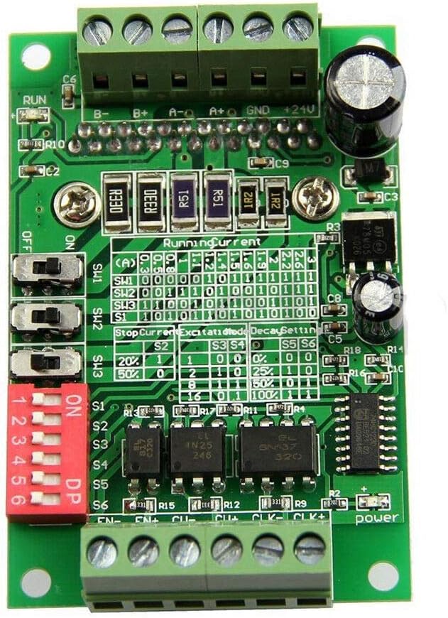
Image: Top view of the TB6560 driver board, highlighting the various connection terminals and DIP switches for configuration. This view helps in identifying where to connect power, motor, and control signals.
Operating Instructions
The TB6560 driver board features DIP switches for configuring the running current, micro-stepping (subdivision), and decay mode. These settings are crucial for optimal motor performance and should be adjusted based on your specific stepper motor and application.
Current Setting (Running Current)
The running current determines the maximum current supplied to the motor windings. This should be set to match or be slightly below your motor's rated current to prevent overheating. Use DIP switches S1, S2, and S3 to set the current level. Refer to the table printed on the board or the image below for specific configurations.

Image: Close-up view of the DIP switches (S1-S6) on the TB6560 driver board. This image helps in identifying the switches used for adjusting running current, micro-stepping, and decay settings.
Example Current Setting (refer to board markings for exact values):
- S1 OFF, S2 OFF, S3 OFF: Lowest Current
- S1 ON, S2 ON, S3 ON: Highest Current (e.g., 3A)
Micro-Stepping (Subdivision) Setting
Micro-stepping allows for smoother motor movement and reduced resonance by dividing each full step into smaller micro-steps. Use DIP switches S5 and S6 to configure the subdivision. The board supports full step, half step, 1/8 step, and 1/16 step.
Example Subdivision Setting (refer to board markings for exact values):
- S5 OFF, S6 OFF: Full Step
- S5 ON, S6 OFF: Half Step
- S5 OFF, S6 ON: 1/8 Step
- S5 ON, S6 ON: 1/16 Step
Decay Mode Setting
The decay mode affects how the current in the motor windings is regulated during chopping. Proper decay mode selection can reduce motor noise and vibration. Use DIP switch S4 to select the decay mode (e.g., Fast Decay, Slow Decay, or Mixed Decay).
Example Decay Setting (refer to board markings for exact values):
- S4 OFF: Slow Decay (or similar)
- S4 ON: Fast Decay (or similar)
Always refer to the markings directly on your TB6560 driver board for the most accurate DIP switch configurations, as variations may exist between manufacturing batches.
Maintenance
The TB6560 driver board is designed for durability and requires minimal maintenance. However, following these guidelines can help ensure its long-term performance:
- Keep Clean: Periodically inspect the board for dust and debris. Use compressed air or a soft brush to gently clean the components, especially the heatsink, to maintain optimal cooling.
- Check Connections: Ensure all wire connections to the terminals are secure and free from corrosion. Loose connections can lead to intermittent operation or damage.
- Environmental Conditions: Operate the board within its specified temperature and humidity ranges. Avoid exposure to moisture, corrosive substances, or extreme temperatures.
- Heatsink Integrity: Ensure the heatsink is firmly attached and not obstructed, allowing for proper heat dissipation.

Image: Bottom view of the TB6560 driver board, clearly showing the heatsink. This component is crucial for dissipating heat and maintaining the board's operational stability.
Troubleshooting
If you encounter issues with your TB6560 driver board, refer to the following common problems and solutions:
- Motor Not Moving or Erratic Movement:
- Check all power connections to ensure they are secure and the voltage is within the 10V-35V range.
- Verify motor wiring. Incorrect phase connections will prevent proper operation.
- Ensure control signals (PUL, DIR, ENA) are correctly connected and being sent from your controller.
- Confirm DIP switch settings for current and subdivision match your motor and application.
- Check if the motor current exceeds 3A; this board is not suitable for motors over 3A.
- Board Overheating:
- Ensure the heatsink is clean and unobstructed.
- Verify the running current setting. If it's too high for your motor, it can cause excessive heat. Reduce the current setting.
- Ensure adequate ventilation around the driver board.
- Check if the motor is stalled or overloaded, which can draw excessive current.
- Motor Vibrates but Does Not Rotate:
- This often indicates incorrect motor phase wiring. Double-check the connections to A+, A-, B+, B-.
- Ensure the pulse signal (PUL) is being received correctly.
- No Response from Board:
- Check if the power supply is active and providing the correct voltage.
- Inspect for any visible damage to the board or components.
- Ensure the enable signal (ENA) is correctly configured and not disabling the driver.
Safety Information
Please read and follow these safety precautions to prevent injury and damage to the product:
- Electrical Safety: Always disconnect power before making or changing any electrical connections. Work with electricity carries inherent risks.
- Voltage Range: Do not exceed the specified input voltage range of DC 10V-35V. Overvoltage can permanently damage the board.
- Polarity: Ensure correct polarity when connecting the power supply. Reverse polarity will damage the board.
- Motor Current: Do not use this driver board with stepper motors that require more than 3A.
- Heat: The heatsink can become hot during operation. Avoid touching it directly to prevent burns. Ensure adequate airflow for cooling.
- Environment: Use the board in a dry, non-condensing environment, free from conductive dust and corrosive gases.
- Professional Installation: If you are unsure about any aspect of installation or operation, consult a qualified professional.