1. Introduction
This manual provides essential information for the safe and efficient operation of the Walfront AT3-1500X Variable Frequency Drive (VFD). The AT3-1500X is a high-performance 3-phase adjustable speed controller designed for motor speed control applications, offering a wide speed regulating range and robust performance. Please read this manual thoroughly before installation, operation, or maintenance.
2. Safety Precautions
Failure to follow these safety instructions may result in death, severe injury, or property damage.
- Always ensure the power supply is disconnected before performing any wiring or maintenance.
- Do not connect the U/V/W output terminals directly to the AC power supply. This will cause internal damage to the inverter.
- The inverter must not be installed on flammable surfaces or near flammable materials to prevent fire hazards.
- Ensure the ground terminal of the inverter is properly and securely grounded.
- Avoid installation in environments containing explosive gases to eliminate explosion risks.
- Only qualified professionals should perform wiring and internal inspections. The converter contains high voltage components; do not open the shell casually.

Image: Front view of the VFD showing the safety precautions label.
3. Product Overview
The Walfront AT3-1500X VFD utilizes a unique control method to achieve high performance and a wide speed regulating range. It features excellent anti-trip capabilities and resilience against power fluctuations, temperature, humidity, and dust interference, enhancing overall stability. Optimized PWM control technology and electromagnetic compatibility ensure low noise and minimal electromagnetic interference.

Image: Front view of the Walfront AT3-1500X VFD, showing the display and control panel.
3.1 Key Features
- Comprehensive Protection: Includes over-current, over-voltage, over-heat, overload, under-voltage, and intelligent power module protection.
- Durable Construction: Made from heat and flame-retardant shell material for extended lifespan.
- Efficient Cooling: Equipped with a high-efficiency fan for optimal heat dissipation, prolonging service life.
- Interference Resistance: Designed to resist interference from rough power, temperature, humidity, and dust, ensuring high reliability and stability.
- Responsive Operation: Fast start and stop response with high torque at low speeds.

Image: Side view of the VFD, highlighting the heat sink fins for effective cooling.

Image: Rear view of the VFD, showing the cooling fans and product label with model information.
4. Specifications
| Parameter | Value |
|---|---|
| Model | AT3-1500X |
| Application Range | Universal |
| Power Supply Phase | Three Phase |
| Rated Current | 4A |
| Rated Voltage | AC380V (Three Phase) |
| Suitable Motor Power | 1.5kW |
| Filter | Built-in Filter |
| DC Power Supply | Voltage Type |
| Control Method | V/F Closed Loop |
| Output Voltage Adjustable Method | PWM Control |
| Dimensions (L x W x H) | Approx. 18 x 12.5 x 12.5 cm (7 x 4.9 x 4.9 inches) |
| Weight | Approx. 1431g (3.15 pounds) |
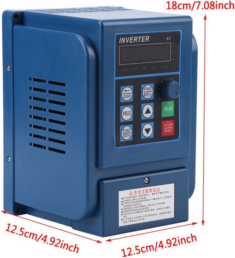
Image: Front view of the VFD with key dimensions indicated.
5. Setup and Installation
5.1 Environmental Considerations
- Install the VFD in a clean, dry, and well-ventilated area.
- Avoid direct sunlight, excessive dust, corrosive gases, and flammable materials.
- Ensure ambient temperature is within the specified operating range.
5.2 Wiring Instructions
Proper wiring is crucial for safe and correct operation. Refer to the wiring diagram below and ensure all connections are secure and correctly terminated. Always disconnect power before wiring.

Image: Close-up view of the VFD's input and output wiring terminals.

Image: Detailed view of the VFD's wiring terminals, showing input (380V) and three-phase motor connections (R, S, T, W, V, U).
- Power Input (R, S, T): Connect the three-phase 380V AC power supply to these terminals.
- Motor Output (U, V, W): Connect the three-phase motor to these terminals.
- Grounding: Ensure the ground terminal is connected to a reliable earth ground.
- Control Terminals: Refer to the detailed wiring diagram in the full product manual for specific control signal connections (if applicable).
6. Operating Instructions
The VFD features a user-friendly control panel for easy operation and parameter adjustment.
6.1 Control Panel Buttons

Image: Diagram illustrating the functions of each button on the VFD control panel.
- 5 Digits LED Display: Shows operational parameters and settings.
- DISP (Movement Key): Switches monitoring parameters in monitoring state; moves data frame to edit bit in the second-level menu.
- PROG (Programme Key): Exits the current state, switches to another state, mainly used to switch to the monitoring state.
- FUNC/DATA (Function/Save Key): Enters the menu step by step, saves the set parameters.
- ▼ (Minus Key): Short/Long press decreases data and function code.
- ▲ (Plus Key): Short/Long press increases data and function code.
- FWD/REV (CW/CCW Key): Press to run (CW operation), release to stop. For CCW operation, refer to advanced settings.
- STOP/RESET Key: Stops the operation of the VFD; recovers from previous wrong interface.
- RUN (Operation Key): Initiates operation.
6.2 Function Indicators

Image: Diagram explaining the various function indicators on the VFD display.
- FWD: Indicates the VFD is operating in the Clockwise (CW) direction.
- REV: Indicates the VFD is operating in the Counter-Clockwise (CCW) direction.
- r/min: Indicates that the motor's Revolutions Per Minute (RPM) is displayed.
- A: Indicates that the current (Amperes) is displayed.
7. Maintenance
Regular maintenance ensures the longevity and optimal performance of your VFD.
- Cleaning: Periodically clean the VFD's exterior and cooling fins to prevent dust accumulation, which can hinder heat dissipation. Use a soft, dry cloth.
- Fan Inspection: Check the cooling fan for proper operation and ensure it is free from obstructions. Replace if noisy or not functioning correctly.
- Terminal Check: Regularly inspect wiring terminals for tightness and signs of corrosion. Loose connections can cause overheating and malfunction.
- Environmental Check: Ensure the operating environment remains within specified temperature and humidity limits.
- Professional Inspection: For internal components, professional inspection is recommended at regular intervals.
8. Troubleshooting
This section provides solutions for common issues. For complex problems, contact technical support.
| Problem | Possible Cause | Solution |
|---|---|---|
| VFD does not power on | No input power; Blown fuse; Incorrect wiring | Check power supply; Replace fuse; Verify wiring connections. |
| Motor does not run | Incorrect motor wiring; Parameter settings incorrect; Overload condition | Check motor connections (U, V, W); Verify VFD parameters; Reduce motor load. |
| Over-current fault | Motor overload; Short circuit in motor or wiring; Rapid acceleration/deceleration | Check motor load; Inspect motor and wiring; Adjust acceleration/deceleration times. |
| Over-voltage fault | High input voltage; Rapid deceleration of high inertia load | Check input voltage; Increase deceleration time; Consider braking resistor if necessary. |
| Over-heat fault | Insufficient cooling; Blocked fan; High ambient temperature | Clean VFD and fan; Ensure proper ventilation; Reduce ambient temperature. |
9. Warranty and Support
Walfront products are designed for reliability and performance. For warranty information, please refer to the purchase documentation or contact your retailer. For technical assistance or support, please reach out to Walfront customer service through the official channels provided at the time of purchase.