1. Introduction
The Makeronics Solderless 3220 Breadboard Complete Kit is designed for rapid prototyping and experimentation with electronic circuits without the need for soldering. This kit allows for easy insertion and removal of electronic components, making it ideal for learning, testing, and developing various digital and analog circuits. Components can be reused, saving time and resources during circuit assembly and debugging.
2. Product Overview
The core of this kit is the 3220 tie-point breadboard, featuring an ABS plastic housing and phosphor bronze nickel-plated spring clips for reliable connections. It is mounted on a black aluminum back plate for stability. The breadboard is designed to accept a variety of wire sizes (AWG: 20-29) and includes colored coordinates for simplified component placement. Pins are clearly identified by numbered rows and columns.
The kit also includes a comprehensive set of jumper wires to facilitate connections between components.

Figure 2.1: Detailed view of the 3220 tie-point breadboard layout, highlighting the connection points and labeling.

Figure 2.2: Internal structure of the breadboard, illustrating the metal contact strips that form electrical connections.
3. Components Included
The Makeronics Solderless 3220 Breadboard Complete Kit includes the following items:
- 1x 3220 Tie-Point Breadboard: Comprising 7 power lanes (700 tie-points) and 4 double strips (2520 tie-points), totaling 3220 test points.
- 1x Black Aluminum Back Plate: Provides a stable base for the breadboard.
- 4x Binding Posts: Coded in red, blue, green, and black for easy identification of power and ground connections.
- 560x U-Shape Pure Copper Jumper Wires: Pre-cut and pre-formed in 14 different lengths (40 pieces each) for various connection distances. Lengths include 2mm, 5mm, 7mm, 10mm, 12mm, 15mm, 17mm, 20mm, 22mm, 25mm, 50mm, 75mm, 100mm, and 125mm.
- 65x 24AWG Male-to-Male Jumper Wires: Multicolored, in lengths of 100mm (49pcs), 150mm (8pcs), 200mm (4pcs), and 250mm (4pcs).
- Rubber Feet and Screws: For securing the breadboard to surfaces and preventing sliding.

Figure 3.1: Overview of all components included in the kit.

Figure 3.2: The 560-piece U-shape pure copper jumper wire kit.

Figure 3.3: The 65-piece male-to-male jumper wire set.
4. Setup
Follow these steps to prepare your breadboard for use:
- Attach Rubber Feet: Secure the provided rubber feet to the corners of the aluminum back plate using the included screws. This prevents the breadboard from sliding during use and protects your work surface. Ensure all feet are firmly attached.
- Install Binding Posts: Insert the four binding posts (red, blue, green, black) into their designated holes at the top of the aluminum back plate. Secure them with the provided nuts and washers. Ensure they are tightened sufficiently to prevent loosening during use. The binding posts are labeled Va, Vb, Vc, and Ground, allowing for multiple voltage inputs.
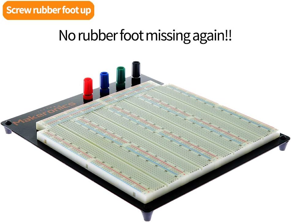
Figure 4.1: Breadboard with rubber feet installed on the aluminum back plate.

Figure 4.2: Binding posts and mounting screws for the rubber feet.
5. Operating Instructions
Using the solderless breadboard for circuit prototyping involves understanding its internal connections:
- Terminal Strips: The main central area of the breadboard consists of multiple rows of five connected tie-points. Components are typically inserted here, with their leads spanning across the central channel.
- Bus Strips (Power Rails): Located along the top and bottom edges of the breadboard, these strips typically run horizontally and are used for power supply connections (positive and negative). The Makeronics 3220 breadboard features 7 power lanes.
- Voltage Inputs: The binding posts (Va, Vb, Vc, Ground) at the top allow for connecting external power sources. Each bus strip supports two different voltage inputs, indicated by gaps in the color marking. This design provides greater control over multiple supply voltages within a single project. If two groups on a bus strip require the same power source, use a jumper wire to bridge them.
To build a circuit:
- Plan Your Circuit: Before inserting components, sketch your circuit diagram and plan the layout on the breadboard.
- Insert Components: Gently push the leads of electronic components (resistors, capacitors, ICs, etc.) into the desired tie-points. Ensure a snug fit without excessive force.
- Make Connections with Jumper Wires: Use the provided U-shape and male-to-male jumper wires to connect components according to your circuit diagram. The varied lengths of the U-shape wires help create neat and organized connections.
- Apply Power: Connect your power supply to the binding posts. Ensure correct polarity (positive to Va/Vb/Vc, negative to Ground).
- Test and Debug: Carefully test your circuit. If it does not function as expected, systematically check connections and component placement.

Figure 5.1: Bus strip configuration for multiple voltage inputs.
6. Maintenance
Proper maintenance ensures the longevity and reliability of your breadboard kit:
- Keep Clean: Regularly inspect the breadboard for dust, debris, or stray wire clippings. Use a soft brush or compressed air to clean the tie-points.
- Handle with Care: Avoid inserting oversized component leads or wires, as this can damage the internal spring clips.
- Store Wires Properly: Keep jumper wires organized to prevent tangling and damage. The provided U-shape wire kit box is useful for this purpose.
- Check Connections: Periodically check the tightness of the binding posts and rubber feet screws.
7. Troubleshooting
If your circuit is not functioning correctly, consider the following troubleshooting steps:
- No Power: Verify that your power supply is connected correctly to the binding posts and is providing the expected voltage. Check for loose connections at the binding posts.
- Intermittent Connections: Ensure all component leads and jumper wires are fully inserted into the breadboard tie-points. Wiggle components gently to check for loose connections.
- Incorrect Wiring: Double-check your circuit against your schematic. Pay close attention to polarity for components like diodes, LEDs, and integrated circuits.
- Component Failure: If possible, test individual components off the breadboard to rule out faulty parts.
- Binding Post Issues: If a binding post feels loose or provides an unreliable connection, ensure its internal components are properly assembled and tightened.
8. Specifications
| Feature | Specification |
|---|---|
| Model | 3220BB |
| Total Tie-Points | 3220 (700 power lanes, 2520 double strips) |
| Binding Posts | 4 (Red, Blue, Green, Black) |
| Wire Compatibility | AWG 20-29 |
| Material | ABS Plastic (housing), Phosphor Bronze Nickel Plated (clips), Aluminum (back plate) |
| Product Dimensions | 11.4 x 9.8 x 0.6 inches |
| Item Weight | 3.55 ounces |
| Jumper Wires Included | 560 U-shape (14 lengths), 65 Male-to-Male (4 lengths) |
9. Support
For technical assistance, product inquiries, or warranty information, please contact Makeronics customer support. Refer to the product packaging or the official Makeronics website for current contact details.