1. Introduction
This manual provides detailed instructions for the installation, operation, and maintenance of the CISA Serie 604 Rack and Pinion Door Closer, model 60450.03.97. This door closer is designed to provide effective and reliable door control for both residential and commercial applications, ensuring smooth and secure door closure.
The CISA Serie 604 features adjustable closing force (EN 2-4) and is suitable for doors weighing up to 85 kg and up to 1100 mm in width. It offers independent adjustments for closing speed and final latching action, ensuring optimal performance in various environments. Its compact design allows for seamless integration with diverse architectural styles.
2. Safety Information
Please read all instructions carefully before installation and use. Failure to follow these instructions may result in injury or damage to the product or property.
- Ensure all components are present and undamaged before beginning installation.
- Always use appropriate tools and safety equipment during installation.
- Do not attempt to modify the door closer. Any modifications will void the warranty and may compromise safety.
- Keep children and pets away from the installation area.
- Ensure the door closer is securely fastened to prevent accidental detachment.
- Adjustments should only be made by qualified personnel to prevent improper operation or damage.
3. Product Overview and Components
The CISA Serie 604 door closer consists of the main body, an arm assembly, and adjustment valves. It is supplied with all necessary fixing screws and a mounting template for straightforward installation.
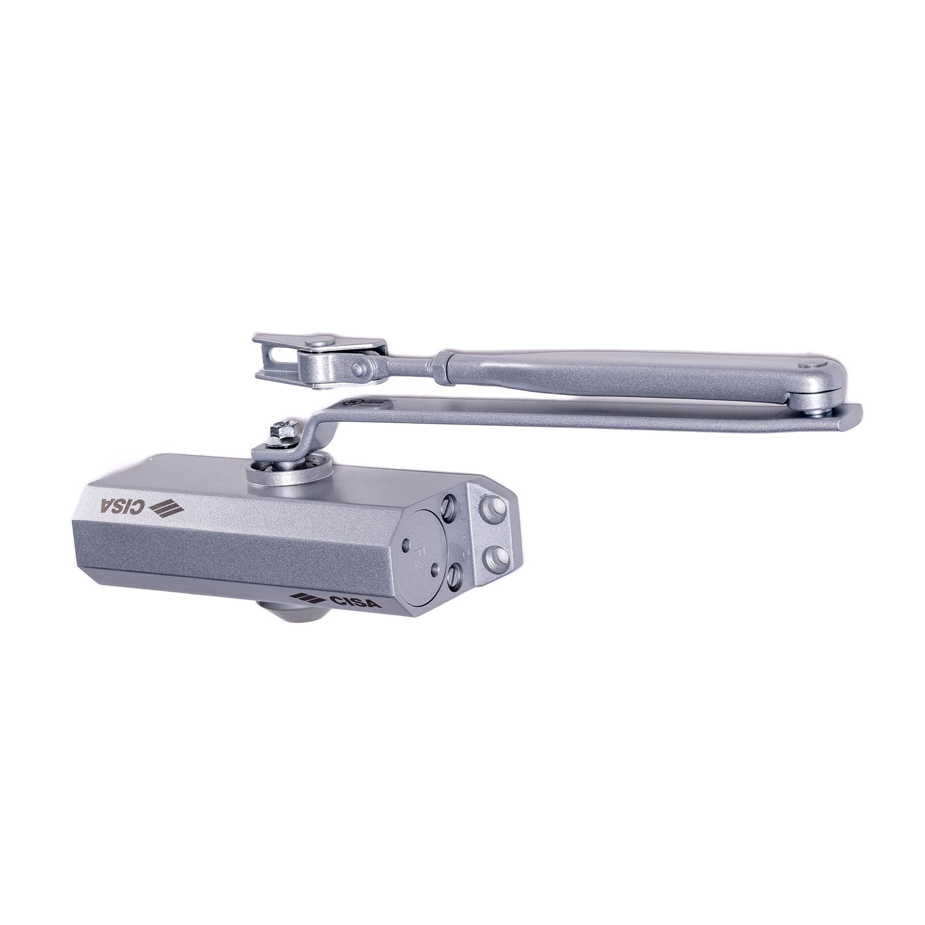
Figure 1: Close-up view of the CISA Serie 604 door closer, highlighting the two adjustment screws for precise control over closing speed and final latching action. The CISA logo is visible at the bottom left.
Key components include:
- Main Body: Contains the rack and pinion mechanism and hydraulic fluid.
- Arm Assembly: Connects the door closer to the door frame or door.
- Adjustment Valves: Two independent valves for controlling closing speed and final latching.
- Mounting Plate/Template: For accurate positioning during installation.
- Fixing Screws: For secure attachment.
4. Setup and Installation
The CISA Serie 604 door closer is designed for quick installation and can be mounted on both right-hand and left-hand doors, for both pull-side and push-side applications. A mounting template is provided to simplify the process.
4.1. Pre-Installation Checks
- Verify the door weight and width are within the specified limits (max 85 kg, max 1100 mm).
- Determine the mounting position (door or frame) and orientation (pull-side or push-side) based on your door type and desired opening angle.
- Ensure the mounting surface is strong enough to support the door closer.
4.2. Mounting Steps
- Positioning: Use the provided mounting template to mark the drilling points on the door or door frame.
- Drilling: Drill pilot holes at the marked positions.
- Attach Main Body: Securely fasten the main body of the door closer using the supplied fixing screws.
- Assemble Arm: Attach the arm assembly to the door closer and the door frame/door, following the specific instructions for your chosen mounting type (pull-side or push-side). Ensure all connections are tight.

Figure 2: Technical drawing illustrating the dimensions and mounting points of the CISA Serie 604 door closer. All measurements are in millimeters, providing precise guidance for installation.
5. Operating Instructions and Adjustments
The CISA Serie 604 door closer allows for independent adjustment of two key functions: closing speed and final latching action. These adjustments are crucial for optimal door performance and safety.
5.1. Adjustment Valves
The door closer features two adjustment valves, typically labeled '1' and '2' or similar, as shown in Figure 1. These valves control different phases of the door's closing cycle:
- Valve 1 (Closing Speed): Controls the speed of the door from its fully open position until approximately 15 degrees from closure. Turning the valve clockwise decreases the speed (slower closing), and counter-clockwise increases the speed (faster closing).
- Valve 2 (Final Latching Action / Backcheck): Controls the speed of the door for the final 15 degrees of closure, ensuring the door latches securely without slamming. It can also provide a backcheck function to prevent the door from opening too quickly or forcefully. Turning clockwise decreases the latching speed/increases backcheck, counter-clockwise increases latching speed/decreases backcheck.

Figure 3: This diagram illustrates the two distinct adjustment sectors. The green sector (up to 80 degrees) represents the main closing speed, while the red sector (final 15 degrees) indicates the final latching action, both independently adjustable.
5.2. Making Adjustments
- Use a suitable screwdriver to turn the adjustment valves.
- Make small adjustments (quarter turns) at a time and test the door's closing action after each adjustment.
- Do not overtighten or loosen the valves excessively, as this can damage the hydraulic mechanism.
- Aim for a smooth, controlled closing action that allows the door to latch without excessive force or speed.
6. Maintenance
The CISA Serie 604 door closer is designed for long-term, maintenance-free operation. However, periodic checks can help ensure its continued performance and extend its lifespan.
- Annual Inspection: Annually inspect the door closer and its mounting screws for any signs of loosening, wear, or damage.
- Cleaning: Keep the door closer clean from dust and debris. Use a soft, damp cloth for cleaning. Avoid abrasive cleaners or solvents.
- Lubrication: No internal lubrication is required. Do not attempt to lubricate any part of the hydraulic mechanism.
- Arm Assembly: Check the arm assembly for any bending or damage. Ensure all pivot points move freely without excessive play.
If any significant wear or damage is observed, contact a qualified technician for inspection and repair or replacement.
7. Troubleshooting
This section addresses common issues you might encounter with your CISA Serie 604 door closer.
| Problem | Possible Cause | Solution |
|---|---|---|
| Door slams shut | Closing speed or final latching speed is too fast. | Adjust Valve 1 (closing speed) and/or Valve 2 (final latching) clockwise in small increments until desired speed is achieved. |
| Door closes too slowly | Closing speed is too slow. | Adjust Valve 1 (closing speed) counter-clockwise in small increments. |
| Door does not latch properly | Final latching speed is too slow or insufficient. | Adjust Valve 2 (final latching) counter-clockwise in small increments to increase latching force/speed. |
| Oil leakage | Damaged seals or internal components. | This indicates a serious issue. The unit cannot be repaired by the user. Contact a qualified technician or replace the unit. |
| Door closer makes unusual noises | Loose mounting screws or damaged internal components. | Check and tighten all mounting screws. If noise persists, contact a qualified technician. |
8. Specifications
| Feature | Detail |
|---|---|
| Model Number | 60450.03.97 |
| Brand | CISA |
| Type | Rack and Pinion Door Closer |
| Adjustable Closing Force | EN 2-4 |
| Max. Door Weight | 85 kg |
| Max. Door Width | 1100 mm |
| Recommended Use | Residential and Commercial Doors |
| Dimensions (L x W x H) | 18 cm x 4 cm x 6 cm |
| Weight | 1.44 kg |
| Material | Aluminum (Body), Steel (Arm) |
| Finish | Aluminum Grey |
| Installation Type | Surface Mounted |
9. Warranty and Support
For information regarding warranty coverage, please refer to the documentation provided at the time of purchase or contact your retailer. CISA products are manufactured to high-quality standards, and proper installation and maintenance ensure long-lasting performance.
For technical support, spare parts, or service inquiries, please contact CISA customer service or your authorized dealer. Ensure you have your product model number (60450.03.97) and purchase details available when contacting support.


