Aexit modle
Aexit Red Illuminated ON-OFF SPST Rocker Switch User Manual
Brand: Aexit | Model: modle
1. Product Overview
The Aexit Red Illuminated ON-OFF SPST Rocker Switch is a single-pole, single-throw (SPST) switch designed for simple ON/OFF control. It features a red neon indicator light that illuminates when the switch is in the 'ON' position. This switch is rated for AC 250V at 16A for resistive loads and comes with 3 pins for easy connection. It is commonly used in various electrical appliances and circuits.
Key Features:
- Product Name: Rocker Switch
- Poles: SPST (Single Pole, Single Throw)
- Terminals: 3 Pins
- Position: On / Off (Two positions)
- Rated Voltage: AC 250V 16A (for resistive load)
- Total Size: 3.3 x 1.3 x 3.6 cm / 1.3" x 0.5" x 1.4" (L*W*H)
- Mounting Size: 2.8 x 1 cm / 1.1" x 0.4" (L*W)
- Color: Black body, Red rocker with neon indicator
- Material: Plastic, Metal
- Package Content: 2 x Rocker Switches
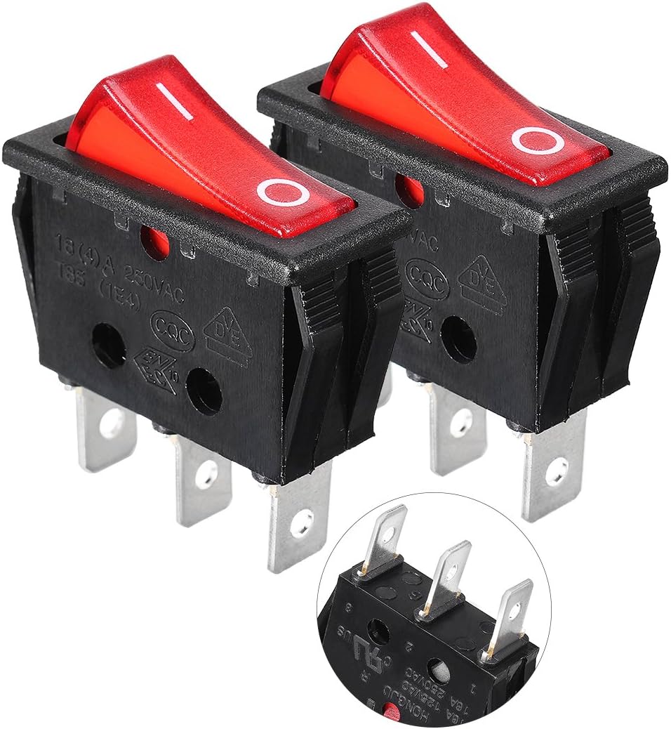
Image 1.1: Two Aexit Red Illuminated ON-OFF SPST Rocker Switches.
2. Safety Information
Please read and understand all safety warnings before installing or operating the switch. Failure to do so may result in injury or damage to the product.
General Warnings:
- Do not allow children to have casual contact with the switch.
- Handle with care; do not shake forcefully.
- Avoid use in extreme temperatures such as open flames and super high temperatures.
Electrical Load Warning:
Very important warning: The ratings on the switch label (AC 250V 16A) are for purely resistive AC loads only. For other types of loads, such as inductive, lamp, motor, or capacitive loads, the current rerating is significantly different. Refer to the specifications table below for detailed current reratings.
DC load current ratings are much lower than AC load ratings. If you need to use this switch with more than 0.5A DC load, please contact the manufacturer or seller for compatibility first to avoid damage or malfunction.
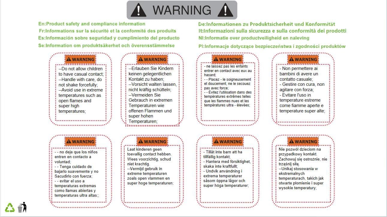
Image 2.1: Product safety and compliance information, including warnings about handling and temperature.
3. Specifications
| Property | Value |
|---|---|
| Manufacturer | Aexit |
| Part Number | f190412ae060905 |
| Size | Actual Size |
| Color | Normal (Black body, Red rocker) |
| Style | Manual |
| Material | Plastic, Metal |
| Power Source Type | Manual |
| Switch Type | Rocker Switch |
| Special Features | Easy Installation |
| Model Number | modle |
| ASIN | B07MRJRST7 |
| Available for purchase since | January 2, 2019 |
Current Rerating for Different Loads (AC 250V):
- Inductive Load: 5.6A
- Lamp Load: 2.88A
- Motor Load: 3.2A
- Capacitive Load: 2.88A
4. Setup and Installation
The Aexit Rocker Switch is designed for easy panel mounting. Ensure the power supply is disconnected before proceeding with installation.
Dimensions:
The total size of each switch is approximately 3.3 cm (length) x 1.3 cm (width) x 3.6 cm (height). The mounting hole size required is approximately 2.8 cm (length) x 1 cm (width). The distance between each pin is 9 mm.

Image 4.1: Detailed dimensions of the Aexit Rocker Switch.
Terminal Configuration:
The switch has 3 pins. Typically, these pins are for input, output, and the ground/neutral connection for the indicator light. Refer to the markings on the switch for specific pin assignments (e.g., '1', '2', '3' or 'L', 'N', 'Load').

Image 4.2: Bottom view of the rocker switch showing the 3-pin terminals.
Installation Steps:
- Prepare Mounting Hole: Cut a rectangular hole in your panel or enclosure according to the specified mounting dimensions (2.8 cm x 1 cm).
- Disconnect Power: Ensure that the power supply to the circuit where the switch will be installed is completely disconnected to prevent electrical shock.
- Wire Connections: Connect the appropriate wires to the 3 pins of the switch. Typically, one pin is for the input power, another for the output to the load, and the third for the neutral/ground connection for the internal indicator light. Ensure connections are secure.
- Insert Switch: Gently push the switch into the prepared mounting hole. The snap-in design will secure it in place.
- Verify Installation: Double-check all wiring connections and ensure the switch is firmly seated in the panel.
- Restore Power: Once installation is complete and verified, restore power to the circuit.
5. Operating Instructions
Operating the Aexit Rocker Switch is straightforward:
- To turn the connected device or circuit ON, press the side of the rocker switch marked with 'I' (or the side that causes the red indicator light to illuminate).
- To turn the connected device or circuit OFF, press the side of the rocker switch marked with 'O' (or the side that causes the red indicator light to turn off).
The red neon light will indicate the 'ON' status of the switch.
6. Maintenance
The Aexit Rocker Switch requires minimal maintenance. Follow these guidelines to ensure its longevity:
- Cleaning: Use a soft, dry cloth to wipe the surface of the switch. Do not use abrasive cleaners, solvents, or harsh chemicals, as these can damage the plastic material.
- Inspection: Periodically inspect the switch for any signs of physical damage, loose connections, or discoloration. If any issues are observed, disconnect power and address them promptly.
- Environment: Ensure the switch is used within its specified temperature and humidity ranges to prevent premature wear or failure. Avoid exposure to excessive dust or moisture.
7. Troubleshooting
If you encounter issues with your Aexit Rocker Switch, consider the following troubleshooting steps:
- Switch Not Activating:
- Check if the power supply to the circuit is active.
- Verify all wire connections are secure and correctly terminated.
- Ensure the load connected to the switch is not exceeding its rated current capacity, especially for non-resistive loads (refer to Section 3: Specifications).
- Indicator Light Not Illuminating:
- Confirm the switch is in the 'ON' position.
- Check the wiring to the indicator light pin (usually the third pin).
- The indicator light may be damaged; if the switch still functions, the light itself might need replacement.
- Overheating or Burning Smell:
- Immediately disconnect power.
- This indicates an overload or short circuit. Re-evaluate your circuit design and ensure the switch is appropriate for the connected load. Do not use the switch if it shows signs of damage from overheating.
If the problem persists after troubleshooting, it may indicate a faulty switch or a more complex electrical issue. Consult a qualified electrician or contact customer support.
8. Warranty and Support
Specific warranty information for this product is not provided in this manual. For details regarding warranty coverage, return policies, or technical support, please refer to the product listing on the retailer's website or contact the seller directly through your purchase platform.
When contacting support, please have your product model number (modle) and ASIN (B07MRJRST7) ready for faster assistance.