1. Product Overview
The Jolooyo DM103AH is a versatile PWM DC motor speed controller designed for driving DC brush motors up to 2000W. It supports both AC15-110V (50/60Hz) and DC+20V to DC+150V input voltages. This controller can be integrated with motion control cards such as MACH3 or PLC systems for joint control, or it can operate independently. It offers speed control, on/off functionality, positive/reverse direction control, locked rotor alarm output, overcurrent protection, short circuit protection, and status indication.
2. Safety Information
Important Safety Note: When controlling motor commutation (changing direction), ensure the motor has completely stopped before sending the commutation signal. Failure to do so may result in fuse damage or motor vibrations. Always prioritize safety during operation and wiring.
The maximum input voltage for AC is 110V. Do not exceed this limit. The device is designed for non-capacitive loads within 2KW.
3. Product Features
- Wide power supply range: AC15-110V (50/60Hz) or DC+20V to DC+150V.
- Compatible with various DC brush motors up to 2000W.
- Designed for integration with motion control cards (e.g., MACH3, USBCNC) or PLC for joint control.
- Independent motor control capability.
- Functions include speed control, on/off, positive/reverse direction.
- Protection features: Locked rotor alarm output, overcurrent protection, short circuit protection.
- Multiple speed control input methods: 0-5V, 0-10V, 4-20mA, PWM signal, and external potentiometer.
- Start/stop and reversing interfaces.
- Status indicator for operational feedback.
- Can also drive boiler heating wires, vibration plates, and electromagnetic machine loads.
4. Specifications
| Specification | Value |
|---|---|
| Model | DM103AH |
| Input Voltage (AC) | AC15-110V (50/60Hz) |
| Input Voltage (DC) | DC+20V to DC+150V |
| Maximum Power | 2000W |
| PWM Frequency Range | 800Hz - 30KHz (Default 16KHz) |
| PWM Duty Cycle | 0-100% |
| Minimum Received PWM Signal | 4.3V peak to peak |
| Dimensions | 151 x 97 x 48.5 mm |
| Weight | 0.7 KG |
| Material | Aluminum |
| Manufacturer | Jolooyo |
5. Setup and Installation
5.1. Wiring Diagram
Refer to the following diagram for proper wiring connections. Ensure all connections are secure before applying power.
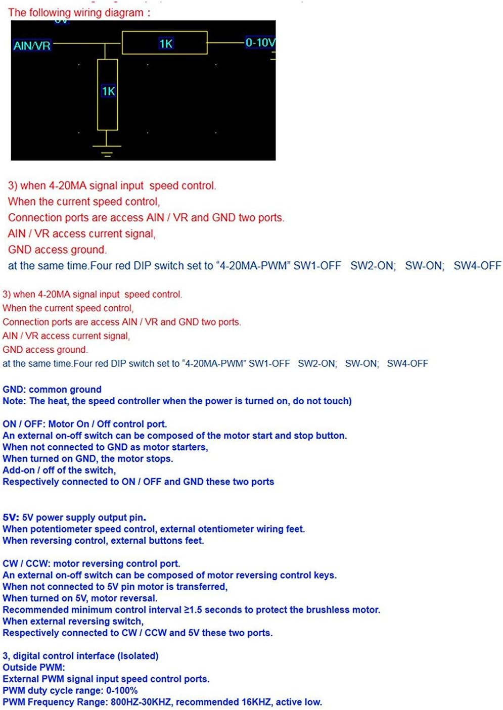
Figure 5.1: Wiring diagram for analog input speed control using a potentiometer.
5.2. Speed Controller Port Definition
The controller features various ports for power, motor connection, and control signals. Understanding these definitions is crucial for correct setup.
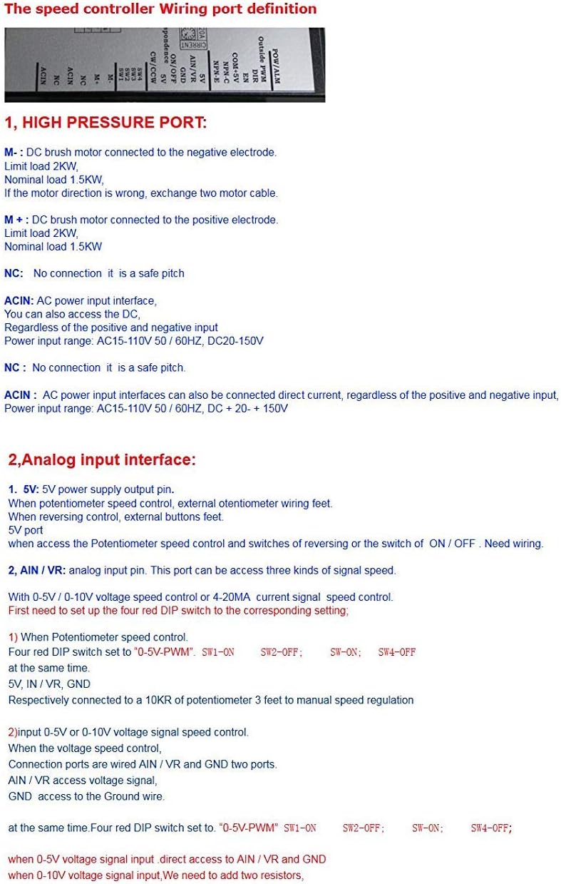
Figure 5.2: Speed Controller Port Definitions.
High Pressure Port Connections:
- M-: DC brush motor negative electrode connection. Limit load 2KW. Nominal load 1.5KW.
- M+: DC brush motor positive electrode connection. Limit load 2KW. Nominal load 1.5KW.
- NC: No connection, it is a safe pitch.
- ACIN: AC power input interface. Can also access the positive and negative input regardless of polarity. Power input range: AC15-110V 50/60HZ, DC20-150V.
Analog Input Interface:
- 5V: 5V power supply output pin. Used for potentiometer speed control, external potentiometer wiring.
- AIN/VR: Analog input pin. This port can be used for three kinds of signal speed control: 0-5V, 0-10V, or 4-20mA.
- GND: Common ground.
- NPN-C: Alarm output NPN transistor collector. Alarm when the transistor is turned on. Maximum current 15mA, voltage range: 3.3-24V.
- NPN-E: Alarm signal output NPN transistor emitter. Alarm when the transistor is turned on. Maximum current 15mA, voltage range: 3.3-24V.
- COM + 5V: Common line for control signals. Designed for 5V level. For PLC24V level control, connect a 1.5K-3K Ohm series resistor ≥1/4W.
- EN: Motor enable control pin. Active low. When the pin is low, the motor stops.
- DIR: Motor direction control port. Active low. Reversing requires a minimum control interval of ≥1.5 seconds.
- Outside PWM: External PWM signal input control ports. PWM duty cycle range: 0-100%. PWM frequency range: 800Hz-30KHz, recommended 16KHz, active low.
5.3. DIP Switch Settings
The controller features DIP switches (SW1, SW2, SW3, SW4) to configure the control interface and PWM frequency. Refer to the table below for settings.

Figure 5.3: DIP Switch Settings for Control Interface.
- 0-5V PWM Signal Input: Set SW1 ON, SW2 OFF, SW3 ON, SW4 OFF. Connect AIN/VR and GND ports.
- 4-20mA PWM Signal Input: Set SW1 OFF, SW2 ON, SW3 ON, SW4 OFF. Connect AIN/VR and GND ports.
- Outside PWM Signal Input: Set SW1 OFF, SW2 OFF, SW3 OFF, SW4 ON.
For 0-5V/0-10V voltage speed control or 4-20mA current signal speed control, first set the four red DIP switches according to the corresponding setting. For potentiometer speed control, connect a 10KΩ potentiometer to 5V, AIN/VR, and GND.
Frequency Potentiometer (PWM-FRQ) PWM Signal Input Settings:
When set to non-external PWM input (manual speed regulation, 0-10V/0-5V voltage speed control, 4-20mA current speed control), the PWM motor control signals are generated internally by the MCU. In this case, the potentiometer can be used to set the PWM frequency for speed regulation. The factory default setting is 16KHz. Generally, it is not advised to change this setting. Adjusting this setting can affect motor noise, working time, and mechanical resonance. If the default settings do not meet specific requirements, this potentiometer can be adjusted. Clockwise rotation increases frequency, counter-clockwise decreases it. Frequency adjustment range: 2-20KHz.
6. Operating Instructions
6.1. Motor Speed Control
The motor speed can be controlled via various input signals as configured by the DIP switches:
- 0-5V / 0-10V Voltage Signal: Connect the signal to AIN/VR and GND.
- 4-20mA Current Signal: Connect the signal to AIN/VR and GND.
- External Potentiometer: Connect a 10KΩ potentiometer to 5V, AIN/VR, and GND for manual speed regulation.
- External PWM Signal: Connect the PWM signal to the 'Outside PWM' port. Ensure the PWM frequency is between 800Hz and 30KHz, with a duty cycle of 0-100%, and a minimum peak-to-peak signal of 4.3V.
6.2. Motor Commutation (Direction Change)
To change the motor's direction (forward/reverse), use the DIR control port. This is an active low input. An external on-off switch can be used for reversing control. Connect two lines to DIR, COM + 5V, and two ports. A recommended minimum control interval of ≥1.5 seconds is required between direction changes to protect the motor.
6.3. Motor Enable/Disable
The EN (Enable) pin controls the motor's on/off state. This is an active low input. When the EN pin is pulled low, the motor stops. An external on-off switch can be used for this function. Connect two lines to EN, COM + 5V, and two ports.
7. Maintenance
The Jolooyo DM103AH motor speed controller is designed for durability and reliable operation. Regular maintenance is generally not required beyond ensuring clean connections and a dust-free environment. Keep the heatsink clear of obstructions to ensure adequate cooling. Periodically inspect wiring for any signs of wear or damage. If the device is exposed to harsh conditions, ensure it is protected from moisture and excessive temperatures.
8. Troubleshooting
- Motor Vibrations or Fuse Burning during Commutation: This typically occurs if the motor direction is changed while the motor is still running. Always ensure the motor has completely stopped before sending a commutation signal.
- Motor Not Responding:
- Check all power connections (ACIN, M+, M-).
- Verify the control signal input (0-5V, 4-20mA, PWM, potentiometer) is correctly connected and within the specified range.
- Ensure DIP switch settings match the chosen control method.
- Check the EN (Enable) pin status; it must not be low if the motor should be running.
- Inspect for any short circuits or overcurrent conditions that might have triggered protection.
- Incorrect Speed Control:
- Confirm the input signal (voltage, current, PWM) is accurate and stable.
- If using a potentiometer, ensure it is correctly wired and functioning.
- Check the PWM-FRQ potentiometer if the default frequency setting has been altered.
9. Warranty and Support
Warranty and specific support information for the Jolooyo DM103AH DC Motor Speed Controller is not specified in the provided product details. For warranty claims or technical assistance, please contact your retailer or the manufacturer directly through their official channels.