Introduction
This manual provides instructions for the safe and effective operation of the Generic UT204 Auto-Ranging AC DC True RMS Digital Handheld Clamp Meter. Please read this manual thoroughly before use and retain it for future reference.
Safety Information
Always adhere to basic safety precautions when using this product to reduce the risk of fire, electric shock, or personal injury. This device is designed for professional use and should only be operated by qualified personnel.
- Do not exceed the maximum input values specified for each measurement range.
- Ensure the test leads are properly connected and in good condition before each use.
- Do not use the meter if it appears damaged or if the case is open.
- Exercise extreme caution when working with voltages above 30V AC RMS, 42V peak, or 60V DC. These voltages pose a shock hazard.
- Replace the battery when the low battery indicator appears to ensure accurate readings.
- Always disconnect the test leads from the circuit before changing functions.
Package Contents
Verify that all items are present in the package:
- 1 x Generic UT204 Digital Clamp Meter
- 1 x Pair of Test Leads
- 1 x English User Manual
Note: A 9V (6F22) battery is required for operation and is not included.
Product Overview
The Generic UT204 is a digital handheld clamp meter designed for measuring AC/DC current, AC/DC voltage, resistance, and other electrical parameters. It features auto-ranging capabilities and True RMS measurement for accurate readings on non-sinusoidal waveforms.
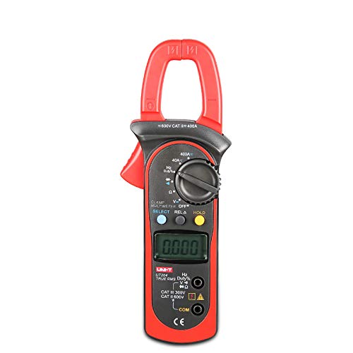
Figure 1: Front view of the Generic UT204 Digital Clamp Meter, showing the clamp jaw, rotary dial, LCD display, and input jacks.
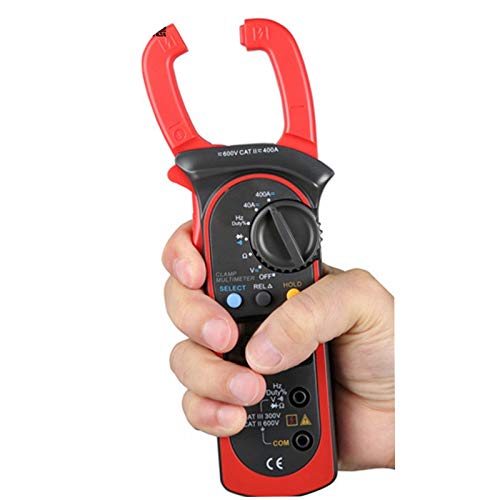
Figure 2: A hand holding the Generic UT204 Digital Clamp Meter, demonstrating its ergonomic design and portability.
Setup
Battery Installation
- Locate the battery compartment cover on the back of the meter.
- Use a screwdriver to open the battery compartment.
- Insert a new 9V (6F22) battery, observing the correct polarity.
- Replace the battery compartment cover and secure it with the screw.
Connecting Test Leads
- Insert the red test lead into the "VΩHz" input jack.
- Insert the black test lead into the "COM" input jack.
- Ensure connections are secure before taking measurements.
Operating Instructions
Power On/Off
Rotate the function dial from the "OFF" position to any desired measurement function to power on the meter. To power off, rotate the dial back to the "OFF" position.
Measuring AC/DC Current (Clamp Measurement)
- Rotate the function dial to the "40A" or "400A" AC/DC current range.
- Press the SELECT button to switch between AC and DC current measurement if necessary.
- Open the clamp jaw by pressing the trigger.
- Enclose only one conductor of the circuit within the clamp jaw. Ensure the jaw is fully closed.
- Read the current value on the LCD display.
Note: For accurate current measurement, only one conductor should be clamped at a time. Clamping multiple conductors will result in a zero reading if the currents are balanced.
Measuring AC/DC Voltage
- Rotate the function dial to the "V~" (AC Voltage) or "V-" (DC Voltage) range. The meter features auto-ranging.
- Connect the red test lead to the positive side of the circuit and the black test lead to the negative side (for DC) or across the circuit (for AC).
- Read the voltage value on the LCD display.
Measuring Resistance
- Rotate the function dial to the "Ω" (Resistance) range.
- Ensure the circuit or component under test is de-energized before connecting the test leads.
- Connect the test leads across the component to be measured.
- Read the resistance value on the LCD display.
Data Hold Function
Press the HOLD button to freeze the current reading on the display. Press it again to release the hold function.
Relative Measurement (RELΔ)
The RELΔ function allows you to store a measurement as a reference value and then display subsequent measurements as a deviation from this reference. Press the RELΔ button to activate/deactivate.
Maintenance
Cleaning
Wipe the meter's case with a damp cloth and a mild detergent. Do not use abrasives or solvents. Ensure the meter is completely dry before use.
Battery Replacement
When the low battery indicator appears on the display, replace the 9V battery as described in the "Battery Installation" section under Setup. Failure to do so may result in inaccurate readings.
Storage
If the meter is not used for an extended period, remove the battery to prevent leakage and damage. Store the meter in a cool, dry place away from direct sunlight.
Troubleshooting
| Problem | Possible Cause | Solution |
|---|---|---|
| No display or faint display | Low or dead battery | Replace the 9V battery. |
| "OL" or "OVER" displayed | Measurement exceeds range | Select a higher range or verify the input is within the meter's capabilities. |
| Inaccurate readings | Poor test lead connection, low battery, or incorrect function selection | Check test lead connections, replace battery, ensure correct function is selected. |
| No current reading (clamp) | Clamping multiple conductors or no current flow | Ensure only one conductor is clamped. Verify current flow in the circuit. |
Specifications
| Parameter | Value |
|---|---|
| Model | UT204 |
| AC Current (A) | 40A/400A (±2.5%+5) |
| DC Current (A) | 40A/400A (±2%+3) |
| AC Voltage (V) | 4V/40V/400V/600V (±1%+5) |
| DC Voltage (V) | 400mV/4V/40V/400V/600V (±0.8%+1) |
| Resistance (Ω) | 400Ω/4kΩ/40kΩ/400kΩ/4MΩ/40MΩ |
| Power | 9V Battery (6F22) |
| LCD Size | 35.6 x 18 mm |
| Product Color | Red and Grey |
| Product Net Weight | 260g |
| Product Size | 208mm x 76mm x 30mm |
| Min. Operating Voltage | 0.4 Volts (DC) |
| Style | Digital |
| True RMS | Yes |
| Auto/Manual Range | Yes |
Warranty and Support
For warranty information or technical support, please refer to the contact information provided by your retailer or the manufacturer's official website. Keep your purchase receipt as proof of purchase.