1. Introduction
This manual provides essential information for the safe and effective use, setup, operation, and maintenance of your YESWELDER 15ft 250Amp MIG Welding Gun Torch Stinger, Model YWTW215M. This product is designed as a replacement for Miller M-25 (part number 169599) MIG welding guns. Please read this manual thoroughly before installation and operation to ensure proper function and safety.

Figure 1.1: YESWELDER 15ft 250Amp MIG Welding Gun Torch Stinger
2. Safety Information
Welding operations involve significant risks. Always adhere to standard welding safety practices to prevent injury or damage. This includes, but is not limited to:
- Wear appropriate personal protective equipment (PPE), including a welding helmet with proper shade, flame-resistant clothing, welding gloves, and safety shoes.
- Ensure adequate ventilation to avoid inhaling welding fumes.
- Protect bystanders from arc rays and sparks.
- Disconnect power to the welding machine before performing any installation, maintenance, or troubleshooting.
- Do not operate welding equipment in damp or wet conditions.
- Keep a fire extinguisher readily available.
3. Package Contents
The YESWELDER 15ft 250Amp MIG Welding Gun Torch Stinger package typically includes:
- 15ft 250Amp MIG Welding Gun Torch Stinger (Model YWTW215M)
- One 0.035" (0.9mm) contact tip (pre-installed)
- Additional 0.035" and 0.045" contact tips
4. Setup
4.1 Connecting the MIG Gun to the Welder
- Ensure the welding machine is powered off and disconnected from the power source.
- Locate the MIG gun connection port on your welding machine. This gun is designed to replace Miller M-25 (169599) models and is compatible with Millermatic 200, 210, 212, 250, 250X, 251, and 252 welders.
- Align the connector of the YESWELDER MIG gun with the port on the welding machine.
- Securely fasten the connector. Ensure a tight connection to prevent gas leaks and ensure proper electrical contact.

Figure 4.1: Dimensions of the MIG Gun Connector
4.2 Installing Consumables
The MIG gun uses standard consumables compatible with Lincoln and Tweco 22-50 Series Nozzles, 32 Insulators, 14 Series Contact Tips, and 52 Series Gas Diffusers.
- Insulator (32 Series): Slide the insulator onto the gun neck.
- Gas Diffuser (52 Series): Thread the gas diffuser onto the gun neck.
- Contact Tip (14 Series): Select the appropriate contact tip for your wire diameter (e.g., 0.035" for 0.9mm wire) and thread it into the gas diffuser.
- Nozzle (22-50 Series): Push or thread the nozzle onto the gun, ensuring it is seated correctly.

Figure 4.2: Exploded View of Consumable Parts

Figure 4.3: Dimensions of Consumable Parts
4.3 Wire Feeding
Follow your welding machine's instructions for feeding the welding wire through the liner of the MIG gun. Ensure the wire diameter matches the contact tip and drive rolls.
5. Operating Instructions
5.1 Basic Operation
Once the MIG gun is connected and consumables are installed, and the welding wire is fed:
- Connect the work clamp to the workpiece.
- Turn on the welding machine and gas supply (if using shielding gas).
- Set the appropriate voltage and wire feed speed on your welding machine according to the material thickness and wire type.
- Position the MIG gun over the workpiece.
- Press the trigger on the gun handle to initiate the arc and wire feed. Release the trigger to stop welding.
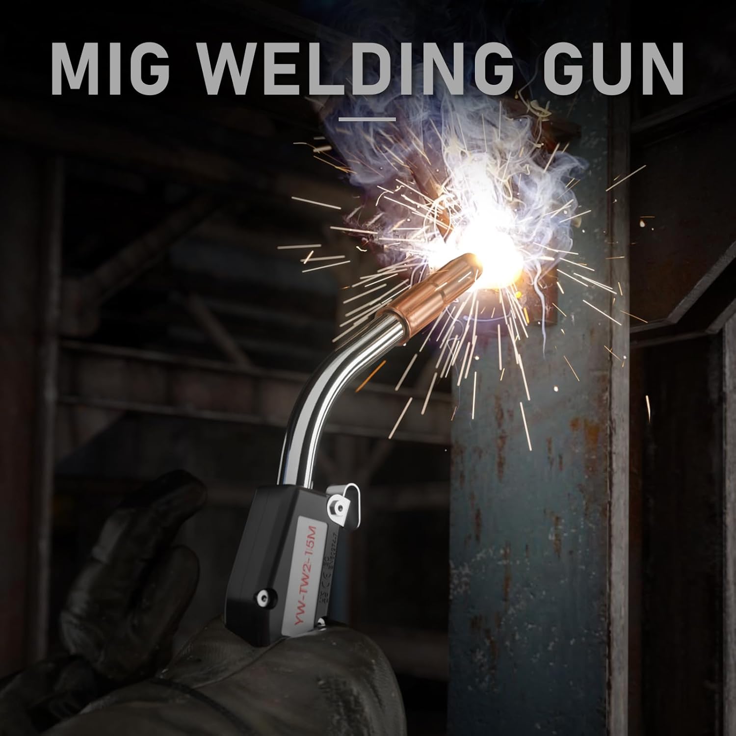
Figure 5.1: MIG Welding Gun in Operation
6. Maintenance
Regular maintenance ensures optimal performance and extends the life of your MIG gun.
- Nozzle Cleaning: Regularly clean spatter from inside the nozzle to maintain proper gas flow. Replace if heavily damaged or clogged.
- Contact Tip Replacement: Replace the contact tip when the opening becomes enlarged or oval-shaped, as this can lead to poor arc stability and wire feeding issues.
- Gas Diffuser and Insulator: Inspect these components for damage or excessive spatter buildup. Replace if necessary to ensure proper shielding gas delivery.
- Liner Inspection: Periodically check the wire liner for kinks or blockages that can impede wire feeding. Replace the liner if it is damaged.
- Cable Inspection: Examine the cable for cuts, abrasions, or signs of heat damage. A damaged cable can pose electrical hazards and affect performance. The cable features a high-conductivity design for efficient power transfer and heat dispersion.

Figure 6.1: Internal Construction of the High-Quality Cable
7. Troubleshooting
| Problem | Possible Cause | Solution |
|---|---|---|
| Poor wire feeding | Incorrect drive roll tension, clogged liner, wrong contact tip size, kinked cable. | Adjust drive roll tension, clean or replace liner, ensure correct contact tip, inspect cable for damage. |
| Excessive spatter | Incorrect voltage/wire speed, dirty workpiece, worn contact tip, insufficient gas flow. | Adjust welding parameters, clean workpiece, replace contact tip, check gas supply and nozzle. |
| No arc | No power to welder, poor ground connection, faulty trigger, wire not contacting workpiece. | Check power supply, ensure good ground, inspect trigger connection, confirm wire feed. |
| Gas leakage | Loose connections, damaged O-rings, cracked gas diffuser or nozzle. | Tighten connections, replace O-rings, replace damaged consumables. |
8. Specifications
- Model: YWTW215M
- Cable Length: 15 feet
- Amperage Rating: 250 Amps (Maximum)
- Compatible Wire Diameter: 0.030" - 0.045" (0.8mm - 1.2mm)
- Material: Copper
- Item Weight: Approximately 7.35 pounds
- Manufacturer: CHANGZHOU CITY KINA WELDING AND CUTTING EQUIPMENT CO.LTD
- Replacement For: Miller M-25 (Part Number 169599)
- Compatible Miller Models: Millermatic 200, 210, 212, 250, 250X, 251, 252
- Consumable Compatibility: Lincoln and Tweco 22-50 Series Nozzle, 32 Insulator, 14 Series Contact Tip, 52 Series Gas Diffuser
9. Warranty and Support
For warranty information, technical support, or to inquire about replacement parts, please contact YESWELDER customer service through their official channels. Refer to your purchase documentation for specific warranty terms and contact details.


