1. Introduction
This manual provides essential information for the safe and efficient installation, operation, and maintenance of the Larsen and Toubro etaCON M 8-Step Automatic Power Factor Correction (APFC) Relay, Model ETACONM008R. Please read this manual thoroughly before installation and operation to ensure proper functionality and to prevent damage to the device or associated equipment.
2. Safety Information
Observe all safety precautions to prevent personal injury and damage to the equipment. Installation and maintenance should only be performed by qualified personnel.
- Always disconnect power before installing, wiring, or servicing the relay.
- Ensure proper grounding of the equipment.
- Verify all connections are secure and correct according to the wiring diagrams.
- Do not operate the device in environments exceeding its specified operating conditions.
- Protect the device from moisture and extreme temperatures.
3. Product Overview
The Larsen and Toubro etaCON M is an 8-step Automatic Power Factor Correction Relay designed for efficient power management. It features a large backlit LCD display for user interaction and monitoring.
Key Features:
- Modular and expandable steps for flexible application.
- Large Backlit LCD display with user-friendly interface for clear readings and easy navigation.
- CT secondary - 1 A / 5 A Site selectable, allowing adaptation to various current transformer ratios.
- Capacitor failure indication for proactive maintenance.
- In-built temperature sensor for monitoring internal conditions.
Front Panel Description:
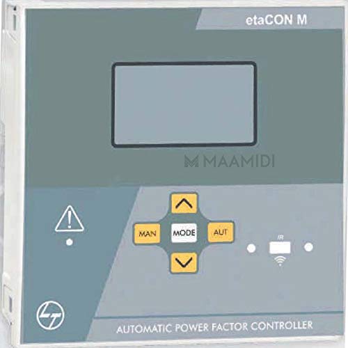
The front panel includes the main LCD display for status and parameter viewing, along with navigation buttons (MAN, MODE, AUT, Up, Down) for configuration and manual control. Indicator lights provide quick visual feedback on the relay's status.
4. Setup and Installation
Proper installation is crucial for the reliable operation of the etaCON M relay. This section details the terminal connections and wiring procedures.
4.1 Terminal Position

The relay features screw-type terminals for secure electrical connections. Refer to Figure 4.1 for the precise location of current input, voltage input, auxiliary supply, and output terminals. The device is designed for DIN Rail mounting.
4.2 Wiring Diagram for MV System

Figure 4.2 provides a comprehensive wiring diagram for integrating the etaCON M relay into a typical MV (Medium Voltage) system. Ensure all connections, including current transformer (CT) and voltage transformer (VT) inputs, auxiliary supply, and output connections to capacitor banks, are made accurately and securely. Pay close attention to phase sequencing and protective device integration (fuses, MCCB).
Default wiring configuration for MV application:
- Voltage measure: phase-to-phase voltage reading L1-L2
- Current measure: L3 phase
- Parameter setting:
- P.04 = L3 phase
- P.05 = L1-L2
- P.30 = 3PH
- P.40 = VT Primary
- P.41 = VT secondary
5. Operating Instructions
The etaCON M relay is designed for automatic operation, but also allows for manual control and parameter adjustment via its user-friendly interface.
5.1 Power On and Initial Display
Upon powering on, the backlit LCD display will illuminate, showing initial system parameters or a welcome screen. The relay will typically enter an automatic operating mode.
5.2 Navigation and Mode Selection
Use the 'MODE' button to cycle through different display screens and parameter menus. The 'MAN' button allows for manual control of capacitor steps, while 'AUT' returns the relay to automatic operation. The 'Up' and 'Down' arrow buttons are used for navigating menus and adjusting parameter values.
5.3 CT Secondary Selection
The CT secondary input can be configured for either 1 A or 5 A, depending on the current transformer used in the installation. This setting is crucial for accurate current measurement and power factor calculation. Refer to the configuration menu accessible via the 'MODE' button and adjust using the 'Up'/'Down' arrows.
5.4 Automatic Operation
In automatic mode, the relay continuously monitors the power factor of the system and automatically switches capacitor steps ON or OFF to maintain the desired power factor target. The in-built temperature sensor helps in optimizing operation and protecting the device.
6. Maintenance
Regular maintenance ensures the longevity and optimal performance of the etaCON M relay.
- Periodic Inspection: Visually inspect the relay and its connections for any signs of damage, loose wiring, or overheating.
- Cleaning: Keep the front panel and ventilation openings clean and free from dust. Use a soft, dry cloth for cleaning. Do not use abrasive cleaners or solvents.
- Firmware Updates: Check with Larsen and Toubro for any available firmware updates that may enhance performance or add features.
7. Troubleshooting
This section provides guidance on common issues that may arise during the operation of the etaCON M relay.
| Problem | Possible Cause | Solution |
|---|---|---|
| Relay not powering on | No auxiliary supply; incorrect wiring; blown fuse. | Check auxiliary supply voltage; verify wiring connections; inspect and replace fuses if necessary. |
| Incorrect power factor readings | Incorrect CT secondary setting; incorrect CT wiring; phase mismatch. | Verify CT secondary setting (1A/5A); check CT polarity and wiring; ensure correct phase connections. |
| Capacitor failure indication | Actual capacitor bank failure; faulty connection to capacitor bank. | Inspect the indicated capacitor bank for damage or reduced capacitance; check wiring to the capacitor bank. |
| Relay not switching steps | Relay in manual mode; parameters not set correctly; faulty output contactor. | Switch to 'AUT' mode; review and adjust operating parameters; check continuity and operation of output contactors. |
If the problem persists after attempting these solutions, contact qualified service personnel or Larsen and Toubro support.
8. Specifications
The following table details the technical specifications for the Larsen and Toubro etaCON M 8-Step APFC Relay, Model ETACONM008R.
| Parameter | Value |
|---|---|
| Brand | Larsen and Toubro |
| Model Number | ETACONM008R |
| Operation Mode | Automatic |
| Connector Type | Screw |
| Contact Material | Copper |
| Contact Type | Normally Open |
| Mounting Type | DIN Rail Mount |
| Contact Current Rating | 5 Amps |
| Item Weight | 500 g |
| Number of Memory Sticks | 1 |
| Date First Available | 30 December 2018 |
9. Warranty and Support
For warranty information, technical support, or service inquiries regarding your Larsen and Toubro etaCON M 8-Step APFC Relay, please contact Larsen and Toubro customer service or visit their official website. Keep your purchase receipt and product model number (ETACONM008R) readily available when seeking support.
Official Website: www.larsentoubro.com