ELECALL EM201
ELECALL EM201 Digital Clamp Meter User Manual
Model: EM201
1. Introduction
The ELECALL EM201 is a 2000-count digital clamp meter designed for measuring AC/DC voltage, AC current, resistance, diode, and continuity. It features stable performance and a compact design, making it suitable for various electrical testing applications. This manual provides detailed instructions for safe and effective operation of the EM201 clamp meter.

Image 1.1: Front view of the ELECALL EM201 Digital Clamp Meter. The device is black with a green clamp jaw and a green rotary switch. The LCD display shows 'OL'.
2. Safety Information
To ensure safe operation and service of the meter, please read this manual carefully before use. Failure to observe safety warnings can result in severe injury or death. Keep this manual for future reference.
- This meter is designed for indoor use only.
- Do not apply more than the rated voltage, as marked on the meter, between the terminals or between any terminal and earth ground.
- Exercise extreme caution when working with voltages above 60V DC or 30V AC RMS. Such voltages pose a shock hazard.
- Before measuring current, ensure the circuit is de-energized and the clamp jaw is properly closed around a single conductor.
- Always disconnect the test leads from the circuit before changing functions.
- Do not operate the meter if it appears damaged or if the insulation is compromised.
- Replace the batteries immediately when the low battery indicator appears to ensure accurate readings.
- This meter is not a True-RMS meter. Consider this characteristic for specific applications.
3. Product Overview
3.1. Meter Components

Image 3.1: Diagram showing the main components of the EM201 clamp meter. Key parts include the Jaw Clamp, Trigger, Rotary Switch, Power button, Data Hold button, Torch button, LCD display, and Test Lead Terminals (COM and VΩ).
- Jaw Clamp: Used for non-contact measurement of AC current. Maximum opening: 28mm (1.1 inches).
- Trigger: Opens and closes the jaw clamp.
- Rotary Switch: Selects the desired measurement function.
- Power Button: Turns the meter ON or OFF.
- HOLD Button: Freezes the current reading on the display.
- Torch Button: Activates the built-in flashlight for illuminating dark work areas.
- LCD Display: Shows measurement readings, units, and function indicators.
- Input Terminals (COM, VΩ): Connect test leads for voltage, resistance, diode, and continuity measurements.
3.2. General Characteristics
- Display Count: 1999
- Jaw Capacity: 28mm (1.1 inches)
- Power: 2 x AAA Batteries (not included)
- Product Color: Green and Gray
- Product Net Weight: Approximately 200g
- Dimensions: Approximately 188mm (Height) x 55mm (Width) x 22mm (Thickness)
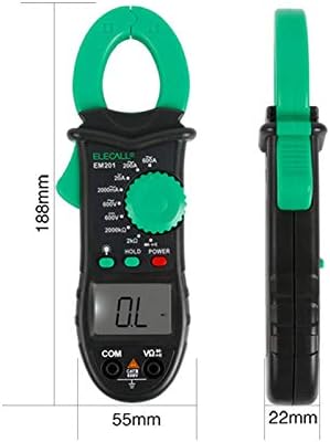
Image 3.2: Side and front view of the EM201 clamp meter illustrating its dimensions: 188mm height, 55mm width, and 22mm thickness.
4. Setup
4.1. Battery Installation
The EM201 requires two AAA batteries for operation. Batteries are not included with the device.
- Locate the battery compartment cover on the back of the meter.
- Use a screwdriver to open the battery compartment.
- Insert two AAA batteries, observing the correct polarity (+ and -) as indicated inside the compartment.
- Replace the battery compartment cover and secure it with the screw.
Note: When the low battery indicator appears on the display, replace the batteries promptly to ensure accurate measurements.
5. Operating Instructions
5.1. Power On/Off
- To turn the meter ON, press the red POWER button.
- To turn the meter OFF, press the red POWER button again.
5.2. Function Selection
Rotate the central green switch to select the desired measurement function. Ensure the switch clicks firmly into place for each selection.
5.3. AC Current Measurement (A)
- Rotate the function switch to the desired AC Current range (2A, 20A, 200A, or 600A).
- Press the trigger to open the clamp jaw.
- Encircle a single conductor with the clamp jaw. Ensure the jaw is fully closed.
- Read the AC current value on the LCD display.
Caution: Only clamp around a single conductor for accurate current measurement. Clamping around multiple conductors will result in an incorrect reading.
5.4. DC Voltage Measurement (V)
- Insert the black test lead into the COM terminal and the red test lead into the VΩ terminal.
- Rotate the function switch to the DC Voltage range (600V).
- Connect the test leads across the circuit or component to be measured.
- Read the DC voltage value on the LCD display. Observe polarity.
5.5. AC Voltage Measurement (V)
- Insert the black test lead into the COM terminal and the red test lead into the VΩ terminal.
- Rotate the function switch to the AC Voltage range (600V).
- Connect the test leads across the circuit or component to be measured.
- Read the AC voltage value on the LCD display.

Image 5.1: The EM201 clamp meter shown with red and black test leads connected to its input terminals, ready for voltage or resistance measurements.
5.6. Resistance Measurement (Ω)
- Insert the black test lead into the COM terminal and the red test lead into the VΩ terminal.
- Rotate the function switch to the Resistance range (2KΩ or 2000KΩ).
- Ensure the circuit or component to be measured is de-energized.
- Connect the test leads across the component.
- Read the resistance value on the LCD display.
Warning: Do not measure resistance on live circuits.
5.7. Diode Test
- Insert the black test lead into the COM terminal and the red test lead into the VΩ terminal.
- Rotate the function switch to the Diode Test position (often indicated by a diode symbol).
- Connect the red test lead to the anode and the black test lead to the cathode of the diode.
- The display will show the forward voltage drop. Reverse the leads; the display should show "OL" (Open Line) for a good diode.
5.8. Continuity Buzzer
- Insert the black test lead into the COM terminal and the red test lead into the VΩ terminal.
- Rotate the function switch to the Continuity Test position (often indicated by a speaker or sound wave symbol).
- Connect the test leads across the circuit or component.
- If the resistance is below approximately 50Ω, the buzzer will sound, indicating continuity.
5.9. Data Hold Function
Press the HOLD button to freeze the current reading on the LCD display. Press it again to release the hold function and resume live readings.
5.10. Backlight and Torch
- Press the Torch button (light bulb symbol) to turn on the LCD backlight and the built-in flashlight.
- Press the Torch button again to turn them off.
6. Specifications
The following table details the technical specifications and measurement ranges of the ELECALL EM201 Digital Clamp Meter.

Image 6.1: Table displaying the basic functions, measuring ranges, resolution, and accuracy for AC Current, DC Voltage, AC Voltage, and Resistance of the EM201 clamp meter.
| Function Name | Measuring Range | Resolution | Accuracy |
|---|---|---|---|
| AC Current (A) | 2 A | 0.001 A | ±(2.5%+12) |
| 20 A | 0.01 A | ±(2%+5) | |
| 200 A | 0.1 A | ±(1.5%+5) | |
| 600 A | 1 A | ±(2%+8) | |
| DC Voltage (V) | 600 V | 1 V | ±(1.0%+3) |
| AC Voltage (V) | 600 V | 1 V | ±(1.5%+5) |
| Resistance (Ω) | 2 KΩ | 1 Ω | ±(1.0%+4) |
| 2000 KΩ | 100 Ω | ±(1.0%+4) | |
| Diode | Yes | ||
| Continuity Buzzer | Yes (approx. <50Ω) | ||
| Data Hold | Yes | ||
| LCD Backlight | Yes | ||
| Low Battery Indication | Yes | ||
7. Maintenance
7.1. Cleaning
Wipe the meter with a damp cloth and a mild detergent. Do not use abrasives or solvents. Ensure the meter is completely dry before use.
7.2. Battery Replacement
When the low battery indicator appears on the display, replace the two AAA batteries as described in Section 4.1. Remove batteries if the meter is not used for an extended period to prevent leakage.
7.3. Storage
Store the meter in a cool, dry place, away from direct sunlight and extreme temperatures. Keep it out of reach of children.
8. Troubleshooting
| Problem | Possible Cause | Solution |
|---|---|---|
| Meter does not power on. | Dead or incorrectly installed batteries. | Check battery polarity or replace batteries. |
| "OL" (Overload) displayed. | Measurement exceeds the selected range. | Select a higher range or ensure the measurement is within the meter's capabilities. |
| Inaccurate readings. | Low battery, incorrect function selected, or poor test lead connection. | Replace batteries, verify function switch position, ensure test leads are securely connected. Remember this is not a True-RMS meter. |
| No continuity beep. | Resistance is too high or circuit is open. | Ensure the circuit is closed and resistance is below 50Ω. |
9. Warranty and Support
This product is manufactured to high-quality standards. For any questions regarding the operation, maintenance, or troubleshooting of your ELECALL EM201 Digital Clamp Meter, please contact the seller or manufacturer for support.
Please refer to your purchase documentation for specific warranty terms and conditions.
Ask a question about this manual
Ask about setup, troubleshooting, compatibility, parts, safety, or missing instructions. Manuals+ will review the question and use this page’s manual context to help answer it.