1. Introduction
This manual provides detailed instructions for the installation, operation, and maintenance of the Sebury NN99 Standalone RFID Access Control System. This device is designed to enhance security for homes, offices, apartments, and factories by controlling door access using RFID cards, passwords, or a combination of both.
2. Product Features
- High quality and security design.
- Sensitive and fast response time.
- Supports up to 1000 standard users.
- Multiple unlock modes: RFID card, password, or RFID card + password.
- Classic appearance with practical functionality.
- Professional design suitable for various environments.
- Integrated doorbell button for connecting an external doorbell.
- Supports single-door control.
- Functions as a standalone keypad; no computer connection required for programming.
- Operates at 125KHz frequency with DC12V power supply.
3. Package Contents
Verify that all items listed below are included in your package:
- RFID Access Control Keypad x 1
- Blue RFID Key Fobs (125KHz) x 10
- English User Manual x 1
- Wire Cable x 1

Figure 3.1: Contents of the Sebury NN99 Access Control System package.
4. Specifications
| Parameter | Value |
|---|---|
| User Capacity | 1000 users |
| Dimensions | 120 x 78 x 22 mm (Length x Width x Thickness) |
| Working Frequency | 125KHz |
| Working Voltage | DC12V |
| Working Current | <100mA |
| Working Temperature | -10°C to +70°C |
| Reading Distance | 0-10cm |
| Relative Humidity | 20% - 90% |
| Unlock Mode | RFID Card, Password, RFID Card + Password |
| RFID Key Fob Frequency | 125KHz |
| RFID Key Fob Material | High quality ABS |
| RFID Key Fob Reading Range | 1-10cm |

Figure 4.1: Keypad dimensions.
5. Product Overview and Components
The access control keypad features several key components for its operation:
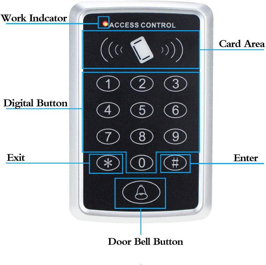
Figure 5.1: Labeled components of the access control keypad.
- Work Indicator: LED light indicating operational status.
- Card Area: Designated area for scanning RFID cards/key fobs.
- Digital Buttons (0-9): Used for entering passwords.
- Exit Button (*): Typically used for programming or specific functions.
- Enter Button (#): Used to confirm entries or programming steps.
- Door Bell Button: Activates an external doorbell when pressed.

Figure 5.2: Internal components and connection points.
The internal analysis reveals the card module, central processor, and connection arrangement. These points are crucial for proper wiring and integration with other access control components.
6. Setup and Installation
Proper installation is critical for the reliable operation of the access control system. It is recommended to have this installed by a qualified technician.
6.1 Wiring Diagram

Figure 6.1: Wiring connections for the access control system.
Refer to the wiring diagram above for connecting the keypad to your access control power supply, electric lock, exit button, and doorbell. Ensure all connections are secure and correctly matched to prevent damage to the device or system malfunction.
- 12V: Connect to the positive (+) terminal of a DC12V power supply.
- GND: Connect to the negative (-) terminal of the DC12V power supply and common ground for other devices.
- PUSH: Connect to the exit button.
- OPEN: Typically for connecting to a door sensor or similar input.
- BEL+ / BEL-: Connect to the positive and negative terminals of an external DC12V doorbell.
- NC / COM / NO: Relay output terminals for connecting to an electric lock. Choose NC (Normally Closed) or NO (Normally Open) based on your lock type.
6.2 Typical Installation Scenario

Figure 6.2: Example installation of the access control system.
The diagram illustrates a common setup where the access controller is mounted near the door, connected to a magnetic lock, an exit button on the inside, and a central power supply unit. Ensure the keypad is mounted at an accessible height and in a location protected from extreme weather conditions if installed outdoors.
7. Operating Instructions
The Sebury NN99 access control system supports various methods for granting access.
7.1 Default Settings
The device typically comes with a default programming password. Refer to the small English user manual included in the package for the specific default password and initial programming steps. It is highly recommended to change the default programming password immediately after installation for security reasons.
7.2 Adding Users (Cards/Passwords)
To add new RFID cards or user passwords:
- Enter the programming mode using the master password.
- Follow the specific instructions in the included manual to add a new user ID.
- For RFID cards, present the card to the card reading area. For passwords, enter the desired password and confirm.
- Exit programming mode.
7.3 Granting Access
Users can gain access using one of the following methods:
- RFID Card: Present a programmed RFID key fob or card to the card reading area. The door will unlock.
- Password: Enter the programmed user password on the keypad, then press the '#' (Enter) button. The door will unlock.
- RFID Card + Password: Present a programmed RFID card, then enter the corresponding password and press '#'. The door will unlock. This method provides a higher level of security.

Figure 7.1: Example of 125KHz RFID key fobs.
7.4 Doorbell Function
If an external doorbell is connected to the BEL+ and BEL- terminals, pressing the doorbell button on the keypad will activate the doorbell.
8. Maintenance
To ensure the longevity and optimal performance of your access control system, follow these maintenance guidelines:
- Cleaning: Wipe the keypad surface with a soft, dry cloth. Avoid using abrasive cleaners or solvents that could damage the finish or electronic components.
- Environmental Conditions: Ensure the device is not exposed to extreme temperatures, direct sunlight for prolonged periods, or excessive moisture. While the RFID key fobs are described as waterproof, the main keypad unit may not be fully weatherproof unless specified.
- Regular Checks: Periodically check all wiring connections for looseness or corrosion. Ensure the electric lock operates smoothly.
- Security: Regularly review and update user access permissions. Change the master password periodically.
9. Troubleshooting
If you encounter issues with your access control system, refer to the following common problems and solutions:
- Device not powering on:
- Check the DC12V power supply connection.
- Verify the power adapter is functioning correctly.
- RFID card not recognized:
- Ensure the card is correctly programmed into the system.
- Confirm the card is a 125KHz EM type.
- Present the card firmly to the card reading area.
- Door not unlocking:
- Check the wiring to the electric lock (NC/NO/COM).
- Verify the power supply to the lock is adequate.
- Ensure the correct access code or card is being used.
- Keypad unresponsive:
- Check for power supply issues.
- If the device is completely frozen, try disconnecting and reconnecting power (power cycle).
- Doorbell not ringing:
- Verify the external doorbell is connected correctly to BEL+ and BEL-.
- Ensure the doorbell itself is functional and receiving power.
For persistent issues, consult the detailed troubleshooting section in the included English user manual or contact customer support.
10. Warranty and Support
This product comes with a standard manufacturer's warranty. Please refer to the warranty card or the official product documentation for specific terms and conditions regarding warranty coverage and duration.
For technical support, product inquiries, or warranty claims, please contact your retailer or the manufacturer directly. Keep your purchase receipt and product model number handy when seeking support.