1. Introduction
This manual provides detailed instructions for the installation, operation, and maintenance of the Twidec MV100-B10 Digital PID Temperature Controller. This device is designed for precise temperature regulation in various industrial and scientific applications. Please read this manual thoroughly before use to ensure safe and optimal performance.
2. Package Contents
The Twidec MV100-B10 package typically includes the following components:
- 1x Twidec MV100-B10 (MY-104) Digital PID Temperature Controller
- 1x Solid State Relay (SSR-25DA)
- 1x K-Type Thermocouple Sensor (Dia: 6mm, Cable Length: 2m/6.6ft)
- 1x White Aluminum Heat Sink
- 1x English Instruction Manual

3. Product Overview
The MV100-B10 features a clear digital display and intuitive controls for easy operation.
3.1 Front Panel Description
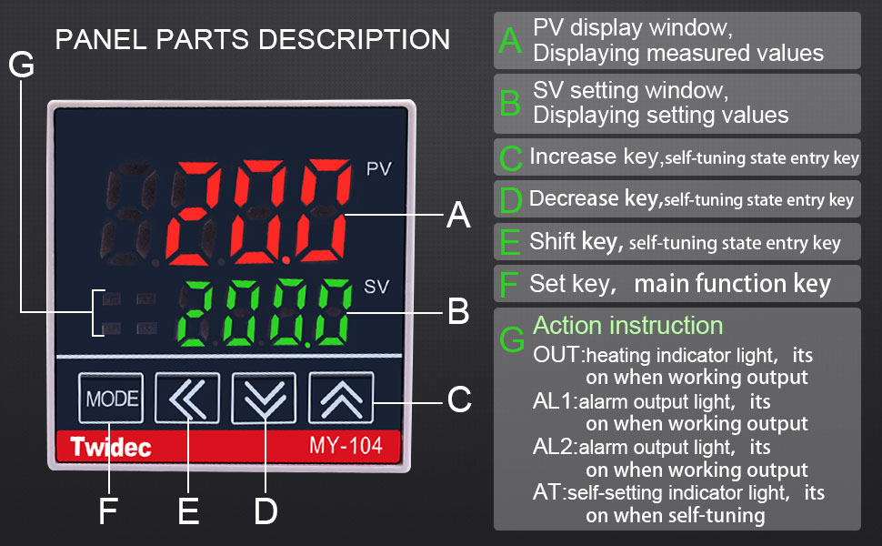
- PV Display Window (Red LED): Displays the measured process value (current temperature).
- SV Setting Window (Green LED): Displays the set value (target temperature).
- MODE Button: Used to cycle through different operating modes and parameter groups.
- Shift Key (<<): Used to shift the digit for setting values.
- Decrease Key (▼): Used to decrease the setting value.
- Increase Key (▲): Used to increase the setting value.
- OUT Indicator: Heating indicator light, illuminates when output is active.
- AL1 Indicator: Alarm output light, illuminates when Alarm 1 is active.
- AT Indicator: Self-tuning indicator light, illuminates during self-tuning process.
4. Specifications
Key technical specifications for the Twidec MV100-B10 PID Temperature Controller and included components:
| Feature | Specification |
|---|---|
| Model | MV100-B10 (MY-104) |
| Power Supply Voltage | AC 85-265V, 50/60Hz |
| Input Type | K-Type Thermocouple (factory default), PT100 (selectable) |
| Output Type | Solid State Relay (SSR) |
| Alarm Mode | 1-way High Deviation Alarm (factory default, configurable) |
| Display Characters | PV: 4-digit 9.9mm Red LED; SV: 4-digit 8mm Green LED |
| Temperature Unit | Celsius or Fahrenheit (factory default to Fahrenheit) |
| Controller Front Panel Dimensions | DIN 48mm(W) x 48mm(L) |
| Mounting Hole Size | DIN 45mm(W) x 45mm(L) |
| SSR Model | SSR-25DA (3-32VDC input, 24-380VAC output) |
| K-Type Sensor Cable Length | 2 meters (6.6 feet) |
4.1 Product Dimensions

5. Installation and Wiring
Proper installation and wiring are crucial for the safe and correct operation of the temperature controller. Always ensure power is disconnected before performing any wiring.
5.1 Mounting the Controller
The controller is designed for panel mounting. Cut a square opening of 45mm x 45mm (1.77in x 1.77in) in your panel. Insert the controller from the front and secure it with the provided fixed buckle on the sides.
5.2 Wiring Diagram
Important: Always refer to the wiring diagram printed on the side of the controller unit itself for the most accurate and up-to-date wiring instructions. Discrepancies may exist between printed manuals and the unit's label. Incorrect wiring can damage the unit or connected equipment.


Wiring Steps:
- Power Supply (Terminals 1 & 2): Connect AC 85-265V power to terminals 1 (Live) and 2 (Neutral).
- K-Type Thermocouple (Terminals 4 & 5): Connect the K-type thermocouple sensor to terminals 4 and 5. Ensure correct polarity: Red wire to terminal 5 (+), Blue wire to terminal 4 (-).
- Solid State Relay (SSR) Output (Terminals 8 & 9): Connect the control terminals of the SSR (3-32VDC input) to terminals 8 (SSR+) and 9 (SSR-) of the controller.
- Alarm Output (Terminals 6 & 7): If using an alarm, connect it to terminals 6 and 7 (AL1).
- SSR Load Wiring: Connect the heating equipment to the output terminals of the SSR (24-380VAC). Ensure the SSR is properly mounted to the heat sink with thermal grease for efficient heat dissipation.


6. Operation
This section details how to power on, set the target temperature, and adjust various parameters of the controller.
6.1 Initial Power-On
Upon initial power-on, the controller will display the measured temperature (PV) and the set temperature (SV). The factory default temperature unit is Fahrenheit. You can change this to Celsius in the parameter settings if desired.
6.2 Setting the Target Temperature (SV)
- Press the MODE button briefly until the SV value starts flashing.
- Use the ▲ (Increase) and ▼ (Decrease) buttons to adjust the desired target temperature.
- Use the << (Shift) button to move the cursor for faster adjustment of specific digits.
- Press the MODE button again to confirm the setting and exit the SV adjustment mode. The controller will now work to maintain the new target temperature.
6.3 Parameter Settings
To access advanced parameters (e.g., PID constants, alarm settings, input type, temperature unit), press and hold the MODE button for several seconds until the first parameter code appears on the PV display. Use the ▲ and ▼ buttons to navigate through parameters and adjust their values. Press MODE briefly to save changes and move to the next parameter, or hold MODE to exit the parameter setting mode.
- Temperature Unit Selection: Locate the parameter for temperature unit (often labeled 'C/F' or similar). Change it to your preferred unit (Celsius or Fahrenheit).
- Input Type: The factory default is K-type. If you are using a PT100 sensor, ensure this parameter is correctly set.
- Alarm Settings: Configure the alarm type and deviation as needed. The factory default is a 1-way high deviation alarm.
- Self-Tuning (AT): For optimal performance, the controller can perform a self-tuning process to automatically determine the best PID parameters for your system. To initiate self-tuning, find the 'AT' parameter and set it to '1' (ON). The AT indicator will light up. Once tuning is complete, the AT indicator will turn off, and the controller will operate with the optimized parameters.
7. Maintenance
The Twidec MV100-B10 is designed for reliable operation with minimal maintenance. However, regular checks can prolong its lifespan and ensure accurate performance.
- Cleaning: Keep the front panel clean and free of dust. Use a soft, dry cloth. Do not use abrasive cleaners or solvents.
- Connections: Periodically check all wiring connections to ensure they are secure and free from corrosion. Loose connections can lead to inaccurate readings or intermittent operation.
- Heat Sink: Ensure the SSR's heat sink is free from dust and debris to maintain efficient heat dissipation. Overheating can damage the SSR.
- Sensor Integrity: Inspect the thermocouple sensor for any physical damage or signs of wear. A damaged sensor can provide incorrect temperature readings.
8. Troubleshooting
If you encounter issues with your Twidec MV100-B10 controller, refer to the following common problems and solutions:
| Problem | Possible Cause | Solution |
|---|---|---|
| "HHH" or "LLL" displayed on PV | Thermocouple open circuit, reversed polarity, or out of range. | Check thermocouple wiring (Red to +, Blue to -). Ensure it's connected to terminals 4 & 5. Verify the thermocouple is not damaged and is within the measurable temperature range. |
| Controller not heating/cooling (OUT indicator off) | Incorrect wiring to SSR, faulty SSR, or SV set incorrectly. | Verify SSR control wiring (terminals 8 & 9) and load wiring. Test SSR functionality. Ensure SV is set to a temperature that requires heating/cooling. Check PID parameters. |
| Inaccurate temperature readings | Incorrect sensor type selected, faulty sensor, or poor sensor placement. | Ensure the input type parameter matches your K-type thermocouple. Replace sensor if faulty. Position sensor correctly in the environment to be measured. |
| Temperature oscillates widely | PID parameters not optimized for the system. | Perform a self-tuning (AT) cycle to optimize PID parameters. |
| Alarm not triggering | Alarm parameters set incorrectly or alarm wiring issue. | Check alarm type and deviation settings in parameters. Verify alarm wiring to terminals 6 & 7. |
9. Warranty and Support
Twidec products are manufactured to high-quality standards. For warranty information, technical support, or service inquiries, please contact your retailer or the manufacturer directly. Keep your purchase receipt as proof of purchase.