
MR CARTOOL L120+
AUTOOL LM120+ Digital Refrigeration Manifold Gauge User Manual
Model: L120+ | Brand: MR CARTOOL
1. Introduction
The AUTOOL LM120+ Digital Refrigeration Manifold Gauge is an intelligent electronic instrument designed for the installation, testing, and maintenance of refrigeration equipment such as air conditioners, refrigerators, and cold storage units. This manual provides comprehensive instructions for the proper use, setup, operation, and maintenance of your device, ensuring optimal performance and longevity.
It features a large LCD display, multiple test modes including dual pressure and dual temperature measurement, pressure leakage testing, and a built-in database of 89 refrigerants for accurate supercooling and superheating calculations.
2. Product Overview and Components
Familiarize yourself with the components of your AUTOOL LM120+ Digital Refrigeration Manifold Gauge.

Figure 2.1: AUTOOL LM120+ Digital Refrigeration Manifold Gauge, including the main unit, hoses, and temperature clamps, packaged with its box.
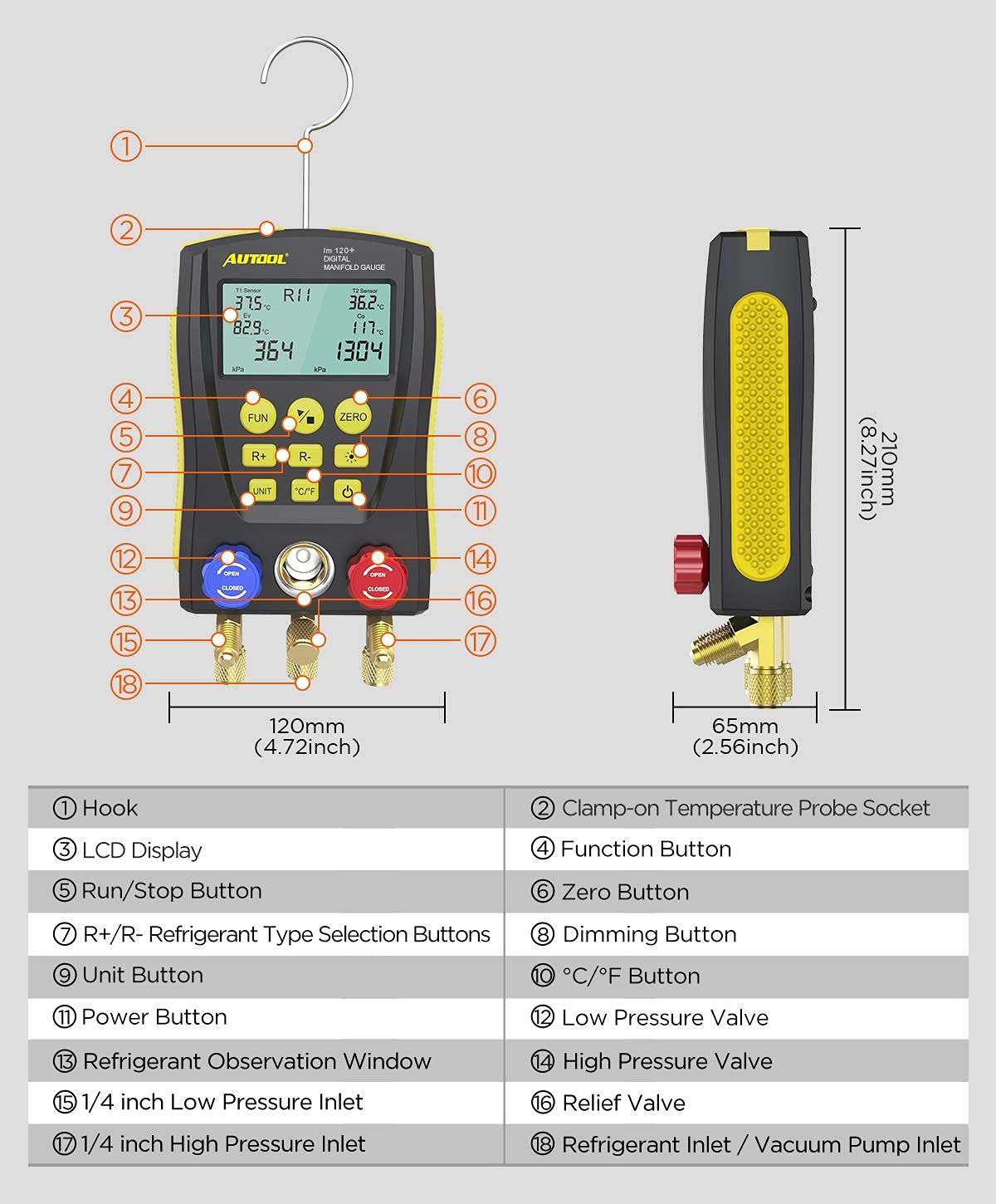
Figure 2.2: Detailed diagram of the LM120+ unit with numbered components and dimensions.
Component Identification:
| No. | Component | Description |
|---|---|---|
| 1 | Hook | For hanging the unit during operation. |
| 2 | Clamp-on Temperature Probe Socket | Connects temperature probes for pipe temperature measurement. |
| 3 | LCD Display | Displays pressure, temperature, refrigerant type, and other data. |
| 4 | Function Button (FUN) | Cycles through various functions and test modes. |
| 5 | Run/Stop Button | Starts or stops measurement processes. |
| 6 | Zero Button (ZERO) | Resets pressure readings to zero. |
| 7 | R+/R- Refrigerant Type Selection Buttons | Selects the type of refrigerant being used. |
| 8 | Dimming Button | Adjusts the brightness of the LCD backlight. |
| 9 | Unit Button (UNIT) | Changes pressure units (e.g., kPa, psi, bar). |
| 10 | °C/°F Button | Toggles temperature display between Celsius and Fahrenheit. |
| 11 | Power Button | Turns the device on or off. |
| 12 | Low Pressure Valve (Blue) | Controls flow to the low-pressure side. |
| 13 | Refrigerant Observation Window | Allows visual inspection of refrigerant flow. |
| 14 | High Pressure Valve (Red) | Controls flow to the high-pressure side. |
| 15 | 1/4 inch Low Pressure Inlet | Connection port for low-pressure hose. |
| 16 | Relief Valve | Releases excess pressure. |
| 17 | 1/4 inch High Pressure Inlet | Connection port for high-pressure hose. |
| 18 | Refrigerant Inlet / Vacuum Pump Inlet | Central connection for refrigerant charging or vacuum pump. |

Figure 2.3: Close-up views of the manifold gauge's connection ports, temperature probe sockets, and the integrated hanging hook.
3. Setup
- Unpacking: Carefully remove the manifold gauge and all accessories from the packaging. Verify that all components listed in the "What's in the Box" section are present.
- Battery Installation: Open the battery compartment on the back of the unit and insert the required batteries (not specified in input, assume standard AA/AAA or internal rechargeable). Ensure correct polarity.
- Hose Connection: Connect the provided high-pressure (red), low-pressure (blue), and service (yellow) hoses to their respective ports on the manifold gauge. Ensure connections are tight to prevent leaks.
- Temperature Probe Connection: If performing temperature measurements, connect the clamp-on temperature probes to the designated sockets on the top of the unit.
- Initial Power On: Press the Power Button (⑂) to turn on the device. The LCD display should illuminate.
- Zeroing the Pressure: Before connecting to a system, press the ZERO button to ensure the pressure readings are calibrated to zero.
4. Operating Instructions
4.1. Selecting Refrigerant Type
The LM120+ has a built-in database of 89 refrigerants. To select the appropriate refrigerant type:
- Press the R+ or R- buttons to scroll through the available refrigerant types (e.g., R11, R12, R22, R134a, R410a).
- The selected refrigerant type will be displayed on the LCD.

Figure 4.1: Setting the refrigerant type and observing flow through the sight glass.
4.2. Pressure and Temperature Measurement
The LM120+ can measure dual pressure (high and low) and dual temperature (high and low pressure pipeline temperature with clamps).
- Connect the high-pressure hose to the high-pressure side of the system and the low-pressure hose to the low-pressure side.
- Attach the clamp-on temperature probes to the respective high and low-pressure pipelines.
- Open the high and low pressure valves on the manifold gauge.
- The LCD will display real-time pressure and temperature readings.
- Press the UNIT button to cycle through pressure units (kPa, psi, bar, etc.).
- Press the °C/°F button to switch between Celsius and Fahrenheit for temperature.

Figure 4.2: Smart Digital Display showing T1 and T2 sensor readings, refrigerant type, and pressure.
4.3. Evaporation Pressure & Temperature Test
This test measures the maximum pressure when the refrigerant changes from liquid to gas and the lowest temperature when the liquid becomes gaseous.

Figure 4.3: Evaporation Pressure & Temperature Test display example.
4.4. Condensing Pressure & Temperature Test
This test measures the minimum pressure when the refrigerant changes from gas to liquid and the maximum temperature when the gas changes to liquid.

Figure 4.4: Condensing Pressure & Temperature Test display example.
4.5. High / Low Pressure Temperature Test
This function displays the temperature of the refrigerant in the high and low pressure pipelines of the air conditioning system.

Figure 4.5: High / Low Pressure Temperature Test display showing T1 and T2 sensor readings.
4.6. Pressure Leakage Measurement
The device can measure pressure leakage, record leakage time, and speed.
- Connect the gauge to the system to be tested for leaks.
- Press the FUN button to navigate to the leakage test mode.
- Follow the on-screen prompts to initiate the test. The display will show the pressure drop over time.
4.7. Refrigerant Charging/Evacuation
Use the central service port (18) for connecting to a vacuum pump for evacuation or a refrigerant tank for charging.
- Evacuation: Connect the yellow hose from the central port to a vacuum pump. Open both high and low pressure valves and start the vacuum pump. Monitor the vacuum level on the display.
- Charging: Connect the yellow hose from the central port to the refrigerant tank. Ensure the system is evacuated. Open the appropriate high or low pressure valve to allow refrigerant into the system, monitoring the pressure.
5. Maintenance
- Cleaning: Wipe the unit with a soft, damp cloth. Do not use abrasive cleaners or solvents. Ensure no liquid enters the ports or display.
- Storage: Store the manifold gauge in a clean, dry place away from direct sunlight and extreme temperatures. Use the provided bag or a suitable case for protection.
- Hose Inspection: Regularly inspect hoses for cracks, wear, or damage. Replace damaged hoses immediately to prevent refrigerant leaks.
- Battery Replacement: If the display dims or the unit does not power on, replace the batteries.
- Calibration: While the unit is designed for high accuracy, if you suspect calibration issues, refer to the manufacturer's support for potential recalibration services.
6. Troubleshooting
| Problem | Possible Cause | Solution |
|---|---|---|
| Unit does not power on. | Low or dead batteries; incorrect battery installation. | Replace batteries, ensuring correct polarity. |
| Inaccurate pressure readings. | Gauge not zeroed; faulty hose connection; sensor issue. | Press the ZERO button before use. Check hose connections for leaks. Contact support if issue persists. |
| Temperature probes not reading. | Probes not properly connected; damaged probes. | Ensure probes are fully inserted into sockets. Inspect probes for damage. |
| Display is dim or unreadable. | Low battery; backlight setting. | Replace batteries. Press the Dimming Button to adjust backlight. |
| Refrigerant leakage during operation. | Loose hose connections; damaged hose O-rings. | Tighten all hose connections. Inspect and replace O-rings if necessary. |
7. Specifications
- Model: L120+
- Dimensions: 14.6 x 4.3 x 11.8 inches
- Weight: 2.4 Pounds
- Material: Acrylonitrile Butadiene Styrene (ABS)
- Manufacturer: AUTOOL
- Built-in Refrigerant Database: 89 types
- Display: Large LCD with backlight
- Interface: 1/4 inch standard
- Power Source: (Not specified, typically batteries)
8. Warranty and Support
MR CARTOOL provides a Three Years Warranty for the LM120+ Digital Refrigeration Manifold Gauge. This warranty covers damages caused by non-human factors. For any parts replacement under warranty, please contact customer support.
Additionally, lifelong maintenance support is offered for this product. For technical assistance, troubleshooting, or warranty claims, please contact MR CARTOOL customer service. You can typically find contact information on the product packaging or the official MR CARTOOL website.
For more information, visit the MR CARTOOL Store on Amazon.
Ask a question about this manual
Ask about setup, troubleshooting, compatibility, parts, safety, or missing instructions. Manuals+ will review the question and use this page’s manual context to help answer it.