1. Introduction
The JDH Labs Tech Integral Electronics Kit with Solar Panel is designed for individuals interested in learning basic electronics. This comprehensive kit includes a variety of components such as a solar panel, battery holder, DC motor, diodes, transistors, LEDs, pushbuttons, resistors, capacitors, and various sensors. It also features integrated circuits like the 555 timer and operational amplifiers, providing versatile tools for educational projects and circuit experimentation. All components are organized within a durable plastic box with removable compartments for convenience.

Image 1.1: The JDH Labs Tech Integral Electronics Kit in its storage box, showing the top label.
2. Kit Contents
This kit includes the following components, carefully selected for educational and experimental purposes:
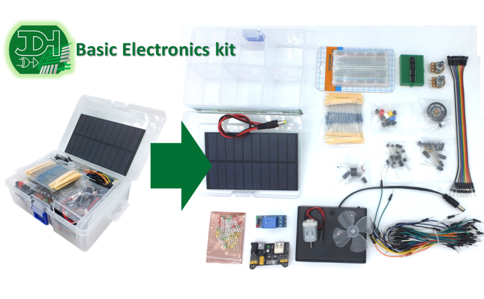
Image 2.1: Overview of all components included in the kit, laid out for inspection.
- Plastic box with 6 optional cells (component organizer)
- Solar Panel 5 ~ 6V / 1.5W
- Small breadboard (400 points)
- 3 ~ 5V DC motor with fan blades
- 8 Ohms / 0.25W Speaker
- Electret microphone 9 * 7 mm
- 6xAA (9V) Battery holder
- Regulator module 5V and 3.3V
- Set of 65 Jumper cables for breadboard
- Set of 10 DuPont Male-Female cables
- 5 Push-Buttons with multicolored covers
- Mini breadboard 170 points
- Relay module 1 channel 10A
- Resistance Kit 1% accuracy 1/4W (ten pieces of each value: 100, 220, 330, 470, 1K, 2K2, 4K7, 10K, 22K, 47K, 100K, 220K, 1M)
- Adjustable 1kOhm Knob Resistor (Potentiometer)
- Adjustable 10kOhm Knob Resistor (Potentiometer)
- Power cable with 5.5 / 2.1mm plug
- 5 * tantalum Capacitors for bypass 0.1uF
- 5 * electrolytic Capacitors of 10uF / 50V
- 5 * electrolytic Capacitors of 100uF / 16V
- 10 * 3mm LEDs diffused RED
- 10 * 3mm LEDs diffused GREEN
- 10 * 3mm LEDs diffused YELLOW
- Infrared LED 5mm
- Infrared phototransistor (flame sensor)
- 10 * General Purpose Diodes 1N4007
- 5 * NPN BC547 transistors
- 5 * PNP BC557 Transistors
- 2 * 555 timer integrated circuits
- 2 * Integrated Circuits Low Voltage Dual Rail-to-Rail Operational Amplifier
- Temperature sensor LM35
- Tilt detector Sensor
- 2 * Light sensors (photoresistor)
- 2 * Thermistors
- Active Buzzer 5V
3. Setup Instructions
Before beginning any project, familiarize yourself with each component. The plastic organizer box helps keep components sorted.
3.1. Power Supply Setup
The kit offers multiple power options:
- 6xAA Battery Holder: Insert six AA batteries (not included) into the battery holder. Ensure correct polarity. This provides 9V output.
- Solar Panel: The 5-6V / 1.5W solar panel can provide power under sufficient light conditions. Connect it to your circuit as needed.
- Regulator Module: Use the 5V and 3.3V regulator module with the breadboard to provide stable power to your circuits from a higher voltage source (e.g., the 9V battery holder or an external power adapter via the power cable).

Image 3.1: The 6xAA battery holder, used to power circuits.

Image 3.2: The solar panel, capable of generating 5-6V / 1.5W.

Image 3.3: The 5V and 3.3V power regulator module mounted on a breadboard.
3.2. Breadboard Usage
The kit includes a small (400 points) and a mini (170 points) breadboard. These are used for prototyping circuits without soldering. Components are inserted into the holes, and jumper wires connect them. The rows are typically connected horizontally in the power rails and vertically in the main component area.
4. Operating Principles
This section provides a brief overview of how to use some of the key components in your electronics kit.
4.1. Basic Components
- Resistors: Limit current flow. Their value is indicated by color bands.
- LEDs (Light Emitting Diodes): Emit light when current flows through them in the correct direction (anode to cathode). Always use a current-limiting resistor with LEDs.
- Diodes: Allow current to flow in one direction only.
- Capacitors: Store electrical energy. Electrolytic capacitors have polarity and must be connected correctly.
- Transistors (NPN/PNP): Act as electronic switches or amplifiers.
- Push-Buttons: Momentary switches that complete a circuit when pressed.
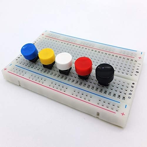
Image 4.1: Multicolored push buttons ready for use on a breadboard.
4.2. Integrated Circuits (ICs)
- 555 Timer ICs: Versatile chips used for timing, pulse generation, and oscillator applications.
- Rail-to-Rail Operational Amplifiers (OPAMPs): Used for amplification, filtering, and other signal processing tasks.
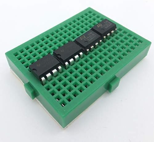
Image 4.2: Various integrated circuits (ICs) mounted on a mini breadboard.
4.3. Sensors
- Temperature Sensor LM35: Provides an analog voltage output proportional to temperature.
- Light Sensors (Photoresistors): Resistance changes with light intensity.
- Tilt Detector Sensor: Detects changes in orientation.
- Infrared Phototransistor (Flame Sensor): Detects infrared radiation, often used for flame detection.
5. Maintenance
Proper care and maintenance will extend the life of your electronics kit components.
- Storage: Always store components in the provided plastic organizer box to prevent loss and damage. Keep the box in a cool, dry place away from direct sunlight.
- Handling: Handle all electronic components with care. Avoid bending leads excessively. Static electricity can damage sensitive components; consider using anti-static precautions if available.
- Cleaning: Keep breadboards and components free from dust and debris. Use a soft, dry brush or compressed air for cleaning.
- Battery Care: Remove batteries from the holder if the kit will not be used for an extended period to prevent leakage. Dispose of used batteries responsibly.
6. Troubleshooting
If you encounter issues with your circuits, consider the following troubleshooting steps:
- No Power: Check battery connections and ensure batteries are charged. Verify power supply connections to the breadboard and regulator module.
- Component Not Working: Double-check component polarity (especially for LEDs, diodes, and electrolytic capacitors). Ensure components are fully inserted into the breadboard.
- Incorrect Wiring: Carefully review your circuit diagram and compare it to your physical connections on the breadboard. A single misplaced jumper wire can prevent a circuit from functioning.
- Resistor Values: Confirm that you are using the correct resistor values for your circuit.
- Short Circuits: Look for any accidental connections between different parts of your circuit that should not be connected.
7. Specifications
| Feature | Specification |
|---|---|
| Package Dimensions | 6.93 x 5.08 x 2.52 inches |
| Item Weight | 15.1 ounces |
| ASIN (Model Number) | B07L74G9FB |
| Batteries Required | 6 AA batteries (not included) |
| Solar Panel Output | 5 ~ 6V / 1.5W |
| DC Motor Voltage | 3 ~ 5V |
| Speaker Rating | 8 Ohms / 0.25W |
| Regulator Module Output | 5V and 3.3V |
| Manufacturer | jdhlabstech |
8. Warranty Information
Specific warranty details for the JDH Labs Tech Integral Electronics Kit are not provided in the product information. Please refer to the seller or manufacturer's official website for any available warranty policies.
9. Support Information
For technical support or inquiries regarding the JDH Labs Tech Integral Electronics Kit, please contact the manufacturer, JDH Labs Tech, directly through their official channels. Contact information may be available on the product packaging or their website.