1. Product Overview
The Miuzei 9G Micro Servo Motor MS18 is a compact and versatile servo designed for various remote-controlled (RC) applications and DIY electronics projects. It features high-quality semi-metal gears for durability and precise control.

Figure 1: Miuzei 9G Micro Servo Motor MS18 with key dimensions (Length: 22.4mm, Width: 12.15mm, Height: 30mm) and included servo horns.
This servo is suitable for micro-robots, robotic arms, RC helicopters, boats, planes, cars, and is compatible with platforms like Arduino and Raspberry Pi.
2. Specifications
Refer to the table below for detailed technical specifications of the Miuzei 9G Micro Servo Motor MS18.
| Feature | Specification |
|---|---|
| Weight | 9 ± 1g |
| Dimensions (L x W x H) | 22.4 mm x 12.15 mm x 30 mm |
| Operating Voltage Range | 4.8V - 6.0V |
| No-load Speed (4.8V) | 0.09 sec/60° |
| No-load Speed (6.0V) | 0.08 sec/60° |
| Stall Torque (4.8V) | 1.4 kg.cm |
| Stall Torque (6.0V) | 1.9 kg.cm |
| Control Angle | 180° (500~2500µs) |
| Operating Temperature | -25°C ~ 70°C |
| Pulse Signal | PWM 50Hz/0.5-2.5ms |
| Amplifier Type | Analog Control |
| Dead Band Setting | 8 µs |
| Gear Type | Semi-Metal Gears |
| Material | PVC, Metal |
3. Setup and Installation
3.1 Package Contents
The package typically includes:
- Miuzei 9G Micro Servo Motor MS18
- Various servo horns (arms)
- Mounting screws

Figure 2: Servo motor with included accessories, including different types of servo horns and mounting screws.
3.2 Wiring Connections
Connect the servo motor to your control board (e.g., Arduino, Raspberry Pi) using the three-wire cable. The wires are color-coded for easy identification:
- Orange Wire: Signal Line (Connect to PWM pin on your control board)
- Red Wire: Positive Pole (Connect to 4.8V-6.0V power supply)
- Brown Wire: Negative Pole (Ground)
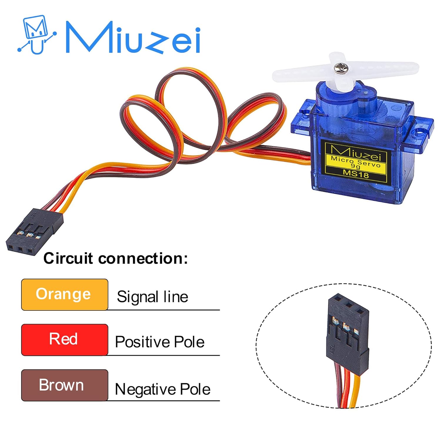
Figure 3: Circuit connection diagram illustrating the color-coded wires for signal, positive power, and ground.
3.3 Mounting the Servo
Use the provided screws to securely mount the servo motor to your application's chassis or structure. Select the appropriate servo horn for your specific needs and attach it to the servo's output shaft.
4. Operating Instructions
The Miuzei 9G Micro Servo Motor MS18 is controlled by Pulse Width Modulation (PWM) signals. The rotation angle is determined by the width of the pulse sent to the signal line.
4.1 Pulse Width Control
The servo operates within a 180-degree range. The standard pulse width for control typically ranges from 0.5ms to 2.5ms, corresponding to 0° to 180° rotation.
- 0.5ms Pulse: Corresponds to 0° position.
- 1.0ms Pulse: Corresponds to 45° position.
- 1.5ms Pulse: Corresponds to 90° (neutral) position.
- 2.0ms Pulse: Corresponds to 135° position.
- 2.5ms Pulse: Corresponds to 180° position.
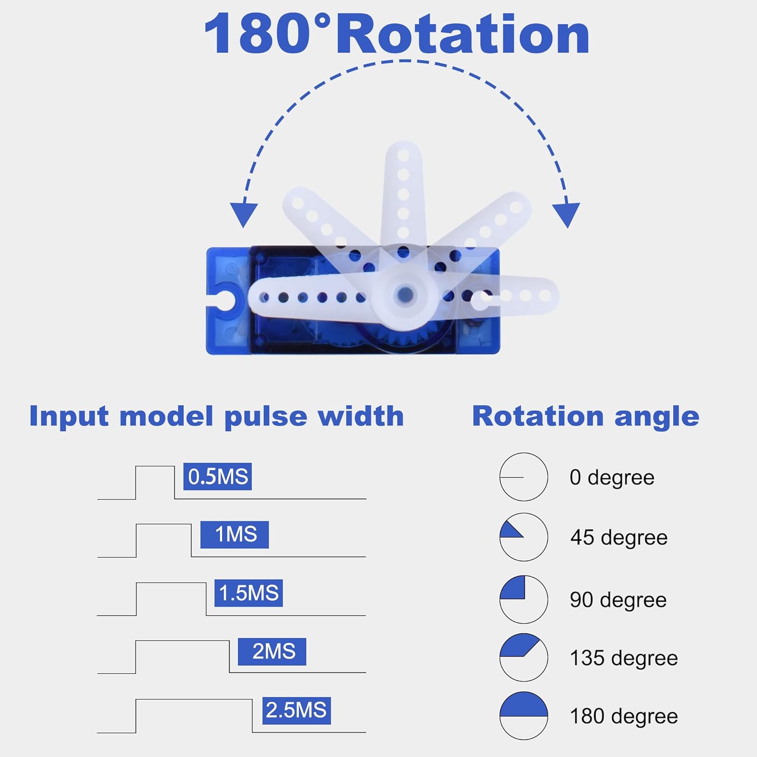
Figure 4: Illustration of pulse width input and corresponding rotation angles for the 180° servo.
For precise control, refer to the documentation of your specific microcontroller or servo library for recommended pulse timings.
4.2 Applications
This micro servo is ideal for applications requiring precise angular movement and compact size. Common uses include:
- Robotic arms and grippers for precise joint control.
- Steering and motion control in RC cars and robots.
- Flight control surfaces in RC planes and helicopters.
- Various DIY electronics projects with Arduino or Raspberry Pi.

Figure 5: Examples of the servo in use for precise joint control in a robotic arm, steering and motion control in an RC car, and reliable flight control in an RC helicopter.
5. Maintenance
To ensure the longevity and optimal performance of your Miuzei 9G Micro Servo Motor MS18, follow these maintenance guidelines:
- Keep Clean: Avoid exposing the servo to dust, dirt, and moisture, which can interfere with the gears and electronics.
- Avoid Overloading: Do not apply excessive force or torque beyond the servo's rated stall torque, as this can damage the gears or motor.
- Proper Voltage: Always operate the servo within its specified voltage range (4.8V-6.0V) to prevent overheating and damage.
- Inspect Connections: Periodically check wiring connections for any signs of wear, corrosion, or loose contacts.
- Gear Inspection: While the servo features semi-metal gears for durability, inspect them occasionally for any signs of wear or damage, especially after heavy use or impacts.
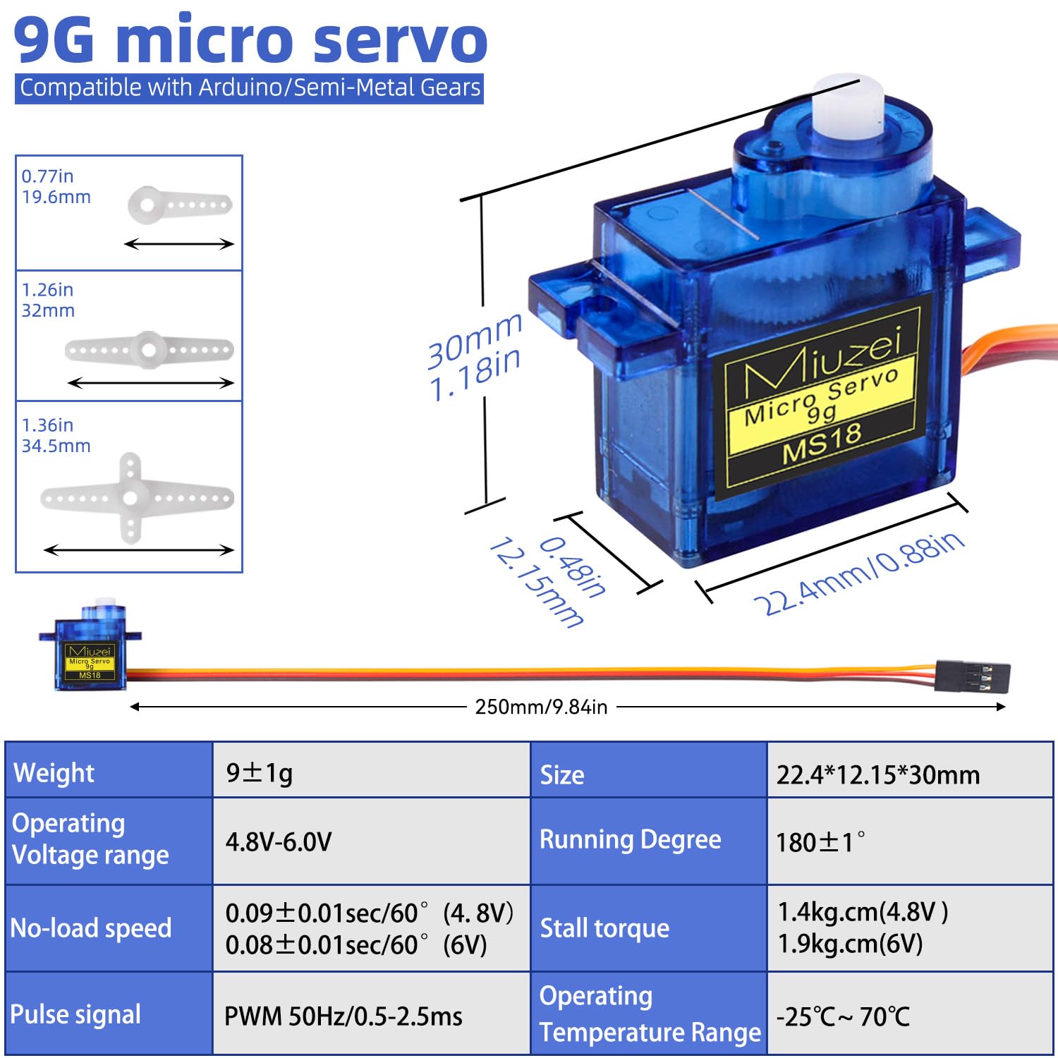
Figure 6: Internal view highlighting the semi-metal gears, which provide stronger torque and durability compared to all-plastic gears.
6. Troubleshooting
If you encounter issues with your Miuzei 9G Micro Servo Motor MS18, consider the following troubleshooting steps:
- Servo Not Responding:
- Check power supply: Ensure the servo is receiving adequate voltage (4.8V-6.0V) and current.
- Verify wiring: Confirm that the signal, positive, and ground wires are correctly connected.
- Test control signal: Use an oscilloscope or a known working servo tester to verify that a valid PWM signal is being sent to the servo.
- Check for mechanical obstruction: Ensure the servo horn or connected mechanism is not physically jammed.
- Erratic Movement or Jitter:
- Power supply issues: Insufficient current from the power supply can cause erratic behavior. Try a separate, dedicated power supply for the servo if sharing with a microcontroller.
- Signal noise: Ensure signal wires are not running parallel to high-current wires, which can induce noise.
- Dead band setting: While the servo has an 8µs dead band, extreme signal noise might still cause jitter.
- Servo Overheating:
- Overload: The servo might be trying to move a load that is too heavy or is being stalled. Reduce the load or ensure free movement.
- Incorrect voltage: Operating above the maximum voltage can cause overheating.
- Continuous operation: Prolonged continuous operation under heavy load can lead to heat buildup. Allow for cooling periods.
- Noisy Operation:
- Normal operation: Some noise is normal for geared servos, especially under load.
- Gear damage: Excessive or unusual noise might indicate damaged or worn gears. Inspect the gears as described in the maintenance section.
7. Warranty and Support
Information regarding specific warranty terms and direct customer support channels for the Miuzei 9G Micro Servo Motor MS18 is not available in the provided product data. Please refer to your purchase documentation or contact the retailer for details on warranty coverage and technical assistance.
8. Official Product Videos
No official product videos from the seller were found in the provided data.


