1. Overview
The Graigar HGM6120NC is an advanced automatic generator controller designed for monitoring and controlling genset systems. It integrates digital, intelligent, and network techniques to provide comprehensive automatic start/stop, data measurement, alarm protection, and remote control capabilities.
This controller features an LCD display with multiple language options for user-friendly operation. It utilizes micro-processing technology for precise measurements, value adjustments, timing, and threshold settings. All parameters can be configured directly from the front panel or via a PC using USB or RS485 interfaces.
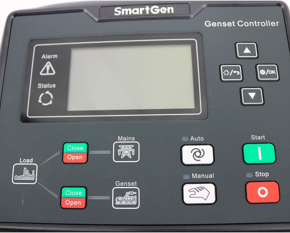
Image 1.1: Front view of the Graigar HGM6120NC Generator Controller, showing the LCD screen and control buttons.
2. Key Features
- Automatic control and monitoring system for gensets.
- Functions include automatic start/stop, data measurement, and alarm protection.
- Supports three remote functions: remote control, remote measure, and remote communication.
- LCD display with optional interface languages: Chinese, English, Spanish, Russian, Portuguese, Turkish, Polish, and French.
- Micro-processing technique for precision measurement, value adjustment, timing, and threshold setting.
- Parameters configurable from the front panel or via USB/RS485 interface with a PC.
3. Setup and Installation
Proper installation is crucial for the safe and reliable operation of the HGM6120NC controller. Ensure all power is disconnected before beginning installation.
3.1 Unboxing and Components
Upon unboxing, verify that all components are present, including the controller unit, mounting hardware, and the instruction manual.

Image 3.1: The HGM6120NC controller shown with its included mounting brackets and screws.
Video 3.1: An overview of the Graigar HGM6120NC Automatic Start Module, demonstrating its physical appearance and included accessories. This video helps in identifying components during unboxing.
3.2 Panel Cutout and Mounting
The controller requires a panel cutout of 186 x 141 mm. Secure the controller using the provided mounting hardware. Ensure adequate space for wiring connections at the rear.

Image 3.2: Angled view of the HGM6120NC, highlighting the front panel and the green terminal blocks for connections on the sides and bottom.
3.3 Wiring Connections
Refer to the detailed wiring diagram on the back of the unit and in the included manual for all electrical connections. Ensure all connections are secure and comply with local electrical codes.
- Power Supply: Connect DC (8-35)V to the designated terminals.
- Sensor Inputs: Connect engine temperature, oil pressure, and fuel level sensors.
- Output Relays: Connect to fuel, crank, auxiliary outputs, and generator/mains contactors.
- Voltage Inputs: Connect genset voltage (U, V, W, N2) and mains voltage (R, S, T, N1).
- Communication Ports: USB and RS485 ports are available for PC connection and remote communication.
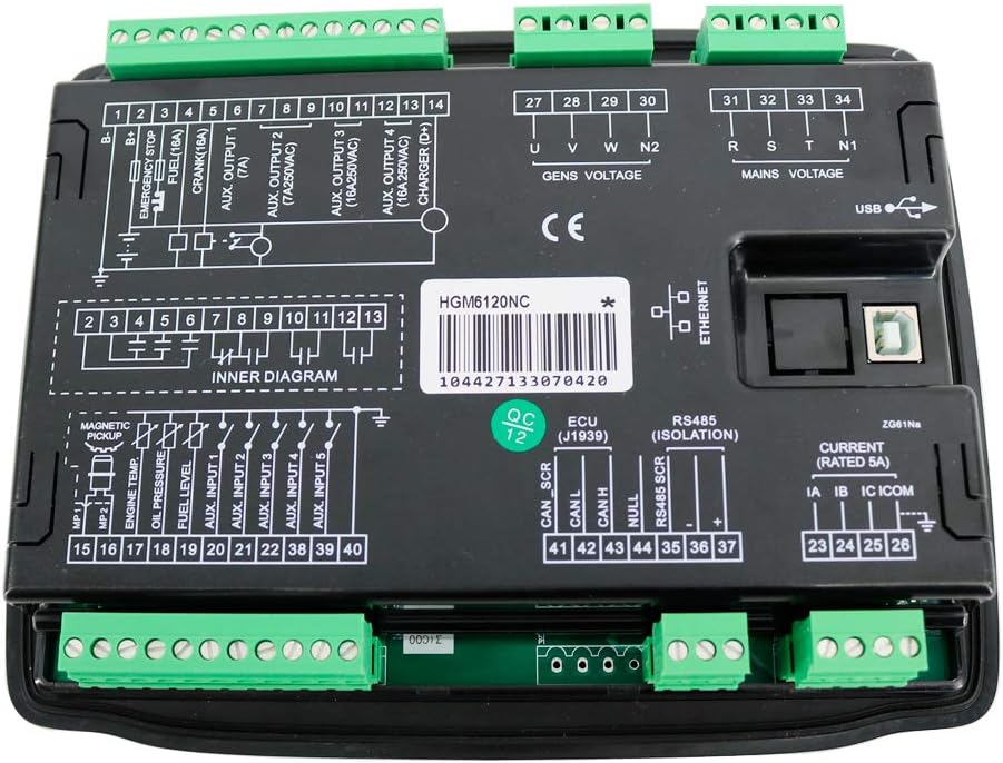
Image 3.3: Rear view of the HGM6120NC controller, displaying the comprehensive wiring diagram and various terminal blocks for power, sensors, outputs, and communication.
4. Operating Instructions
The HGM6120NC controller offers several operating modes and functions accessible via its front panel buttons.
4.1 Front Panel Controls
| Button/Indicator | Function/Description |
|---|---|
| Alarm / Status | Indicators for system alarms and operational status. |
| Load (Close/Open) | Controls the load connection to the power source. |
| Mains (Close/Open) | Controls the connection to the utility mains power. |
| Genset (Close/Open) | Controls the connection to the generator power. |
| Auto | Activates automatic operation mode for the genset. |
| Manual | Activates manual operation mode. |
| Start (Green) | Initiates the generator start sequence in manual mode. |
| Stop (Red) | Stops the generator. |
| Up / Down Arrows | Navigation through menu options and parameter adjustment. |
| Menu / OK | Accesses the menu and confirms selections. |
4.2 Automatic Operation
- Press the Auto button to engage automatic mode.
- The controller will monitor mains power. If mains power fails, the controller will automatically start the genset.
- Once the genset is stable, the controller will transfer the load to the genset.
- When mains power returns, the controller will transfer the load back to the mains and shut down the genset after a cool-down period.
4.3 Manual Operation
- Press the Manual button to engage manual mode.
- Press the Start button to manually start the genset.
- Use the Load Close/Open buttons to manually control load transfer.
- Press the Stop button to manually stop the genset.
5. Maintenance
Regular maintenance ensures the longevity and optimal performance of your HGM6120NC controller.
- Cleaning: Keep the controller's front panel clean and free of dust. Use a soft, dry cloth. Avoid abrasive cleaners or solvents.
- Connection Checks: Periodically inspect all wiring connections for tightness and signs of corrosion. Loose connections can lead to intermittent operation or damage.
- Software Updates: Check the manufacturer's website for any available firmware updates to ensure your controller has the latest features and bug fixes.
- Environmental Conditions: Ensure the operating environment remains within the specified temperature and humidity ranges to prevent damage.
6. Troubleshooting
If you encounter issues with your HGM6120NC controller, consider the following basic troubleshooting steps:
- Controller Not Powering On:
- Verify the DC power supply (8-35V) is correctly connected and providing the correct voltage.
- Check for any blown fuses in the power supply circuit.
- Genset Not Starting Automatically:
- Ensure the controller is in Auto mode.
- Check mains power input connections and settings.
- Verify all engine protection sensors (oil pressure, temperature) are functioning correctly and not triggering false alarms.
- Display Issues:
- If the display is blank or unreadable, check power supply.
- Ensure operating temperature is within the specified range.
- Communication Errors (USB/RS485):
- Verify cable connections are secure.
- Ensure correct drivers are installed on the PC.
- Check communication settings (baud rate, parity) match between the controller and PC software.
For persistent issues, consult the full technical manual or contact Graigar customer support.
7. Specifications
| Parameter | Value |
|---|---|
| Power Supply | DC (8-35)V |
| Case Dimensions | 209 x 166 x 45 mm |
| Panel Cutout | 186 x 141 mm |
| Operating Temperature | (-25~70)℃ |
| Weight | 0.56 kg |
| Material | Plastic |
| Display Type | LCD |
| Manufacturer | Graigar |
8. Warranty and Support
For warranty information, technical support, or service inquiries, please refer to the official Graigar documentation included with your product or visit the manufacturer's official website.
It is recommended to register your product to receive updates and support notifications.