1. Introduction
This service and repair manual provides detailed technical information and procedures for the Kubota B7200, B7200E, and B7200D tractor models. It is designed for technicians and experienced individuals performing repair, overhaul, and troubleshooting tasks. This manual covers various systems and components, offering guidance beyond basic operation and maintenance.
For optimal results and safety, always refer to the specific sections relevant to the task at hand and use appropriate tools and safety equipment.
2. General Information and Specifications
This section provides general information, definitions of manual types, and key specifications for the Kubota B7200 series tractors. Understanding these definitions is crucial for utilizing the manual effectively.
Manual Type Definitions:
- Service Manual: Focuses on repair, overhaul, and troubleshooting procedures.
- Operators Manual: Covers basic maintenance, operation, fluid types, quantities, and adjustments.
- Parts Catalog: Provides exploded views, part names, and factory (OEM) part numbers.
This document serves as a Service Manual.
Tractor Dimensions and PTO Details
Refer to the following diagram for detailed dimensions and Power Take-Off (PTO) specifications for the Kubota B7200 series tractors.

Figure 2.1: Kubota B7200 Series Tractor Dimensions and PTO Details. This image displays various dimensional drawings of the tractor, including overall length, width, height, and specific details for the front and rear PTO assemblies, complete with measurement units in both millimeters and inches.
3. Engine System
This section details the components and service procedures for the engine system of the Kubota B7200 series tractors. It covers various engine parts and their maintenance or repair.
Engine Components Overview
The engine system includes critical components such as the cylinder block, cylinder head, crankshaft, pistons, connecting rods, camshaft, valves, flywheel, air cleaner, and muffler. Each component plays a vital role in the tractor's operation.

Figure 3.1: Engine System Component List. This image shows a section from the manual listing various engine components (e.g., Cylinder Block, Crankshaft, Air Cleaner, Muffler) and their respective page references for detailed information.
Air Cleaner and Muffler Service
Proper functioning of the air cleaner and muffler is essential for engine performance and longevity. The air cleaner prevents contaminants from entering the engine, while the muffler reduces exhaust noise and directs hot gases away.

Figure 3.2: Air Cleaner and Muffler Details. This image provides detailed diagrams and descriptions for the air cleaner and muffler, including their internal components and how they function within the engine system.
Crankshaft and Camshaft Removal
This section outlines the procedures for removing the crankshaft and camshaft, which are critical steps for engine overhaul or repair. Careful attention to detail is required during these processes.

Figure 3.3: Crankshaft and Camshaft Removal Procedures. This image displays pages from the manual illustrating the steps for removing the crankshaft, camshaft, and associated gear case components, complete with visual aids and textual instructions.
4. Lubrication System
The lubrication system ensures all moving engine parts are adequately oiled, reducing friction and wear. This section covers components like the relief valve, bypass valve, oil switch, and oil pump.
Lubrication System Components
Key components of the lubrication system include the relief valve, bypass valve, oil switch, and oil pump. Regular inspection and maintenance of these parts are crucial for engine health.
Figure 4.1: Lubrication System Diagram. This image shows a diagram of the lubrication system, highlighting the oil pump and oil filter, and explaining their roles in circulating oil throughout the engine.
5. Cooling System
The cooling system maintains optimal engine operating temperature. It comprises the water pump, thermostat, radiator, and radiator cap. Proper functioning prevents overheating and ensures engine efficiency.
Figure 5.1: Cooling System Component List. This image displays a section from the manual listing the main components of the cooling system, including the water pump, thermostat, radiator, and radiator cap.
6. Fuel System
The fuel system delivers fuel to the engine for combustion. Key components include the fuel filter, fuel pump, fuel injection pump, injection nozzle, and governor. Regular maintenance ensures clean fuel delivery and proper engine control.
Figure 6.1: Fuel System Component List. This image shows a section from the manual listing the main components of the fuel system, such as the fuel filter, fuel pump, and injection nozzle.
7. Clutch System
The clutch system engages and disengages power from the engine to the transmission. This section provides an overview of the clutch features and its components.
Clutch Features and Components
The clutch assembly includes the flywheel, pressure plate, clutch disc, and release bearing holder. Understanding its operation is vital for smooth power transfer and preventing damage to the transmission.

Figure 7.1: Clutch System Overview. This image displays a page from the manual detailing the features of the clutch system and an exploded view diagram, identifying components like the flywheel, pressure plate, and clutch disc.
8. Transmission System
The transmission system transmits power from the engine to the wheels, allowing for various speeds and torque. This section covers disassembly and servicing procedures for the transmission.
Transmission Disassembly and Servicing
Detailed instructions for disassembling and servicing the transmission are provided to ensure proper repair and reassembly. This includes procedures for removing the transmission case, shafts, and gears.

Figure 8.1: Transmission Disassembly and Servicing. This image shows pages from the manual with diagrams and instructions for disassembling and servicing the tractor's transmission, including views of the transmission case, various shafts, and gear components.
9. Maintenance and Check Points
Regular maintenance is crucial for the longevity and performance of your Kubota B7200 series tractor. This section outlines recommended check points and service intervals.
Periodic Check Points
Perform checks at specified intervals (e.g., every 200, 400, or 500 hours) to ensure all systems are functioning correctly. This includes checking transmission oil, fuel filter, and cooling system components.
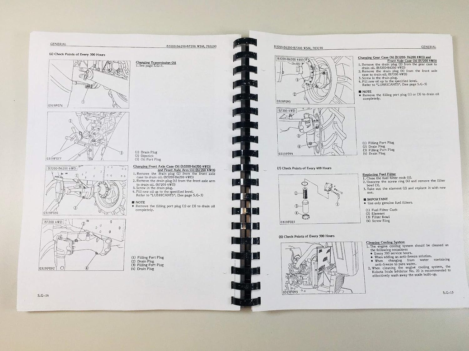
Figure 9.1: General Check Points. This image displays pages from the manual outlining various check points for the tractor, categorized by operating hours (e.g., 200, 400, 500 hours). It includes procedures for checking and changing transmission oil, replacing the fuel filter, and inspecting the cooling system.
10. Troubleshooting
This section provides guidance for identifying and resolving common issues that may arise with the Kubota B7200, B7200E, and B7200D tractors. For complex problems, consult a qualified technician.
General Troubleshooting Steps:
- Identify the Symptom: Clearly define the problem (e.g., engine not starting, unusual noise, fluid leak).
- Check Basic Systems: Verify fuel level, battery charge, and fluid levels.
- Consult Relevant Sections: Refer to the specific system sections (Engine, Fuel, Electrical, etc.) in this manual for detailed diagnostic procedures.
- Inspect for Visible Damage: Look for loose connections, damaged hoses, or worn parts.
- Test Components: Use appropriate testing tools to check component functionality as described in the manual.
11. Warranty and Support
Information regarding product warranty and customer support for this specific service manual is not provided within the available product details. For inquiries related to the manual's content or any potential warranty on the manual itself, please contact the publisher or seller directly.


