Introduction to Your Manual Set
This manual set provides essential information for the Case 580E, 580Se, and 580 Super E Loader Backhoe. It is designed to assist with various aspects of equipment management, from routine maintenance to complex repairs. Understanding the different types of manuals included is crucial for effective use.
Generally, three types of manuals are produced for this equipment, each serving a distinct purpose:
- Service Manual: Focuses on repair procedures, overhaul instructions, and troubleshooting guides for various components.
- Operators Manual: Covers basic maintenance, operational procedures, fluid types, quantities, and adjustments necessary for daily use.
- Parts Catalog: Provides exploded views of assemblies, names of individual parts, and factory (OEM) parts numbers for identification and ordering.
Refer to the specific manual type that aligns with your current needs for accurate and detailed information.

Image: Cover of the comprehensive manual set for Case 580E, 580Se, and 580 Super E Loader Backhoes.
Manual Content Overview
The manual set is organized into several divisions and sections to facilitate easy navigation and access to specific information. Below is an overview of the main sections covered within the manuals.
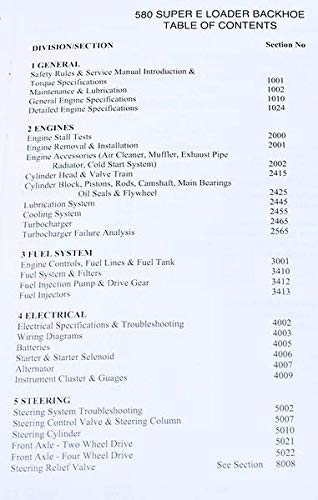
Image: Page 1 of the Table of Contents, detailing sections such as General, Engines, Fuel System, Electrical, and Steering.
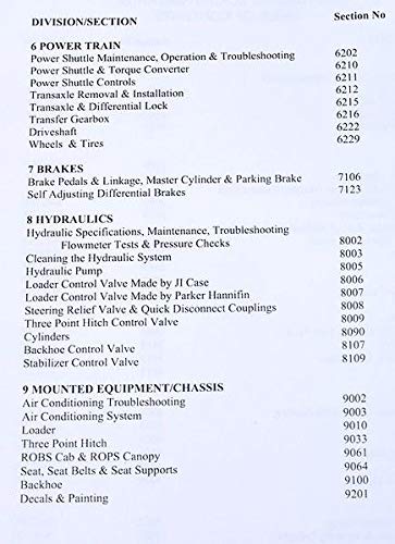
Image: Page 2 of the Table of Contents, detailing sections such as Power Train, Brakes, Hydraulics, and Mounted Equipment/Chassis.
1. General Information
This section provides foundational knowledge for the Case 580E, 580Se, and 580 Super E Loader Backhoe. It includes safety rules, service manual introduction, torque specifications for various fasteners, general maintenance and lubrication guidelines, and detailed engine specifications. Adhering to these guidelines is essential for safe operation and longevity of the equipment.
- Safety Rules & Service Manual Introduction
- Torque Specifications
- Maintenance & Lubrication
- General Engine Specifications
- Detailed Engine Specifications
2. Engines
The engine section covers all aspects of the loader backhoe's power unit. It includes procedures for engine stall tests, removal and installation, and maintenance of engine accessories such as the air cleaner, muffler, exhaust pipe, radiator, and cold start system. Detailed information on the cylinder head, valve train, cylinder block, pistons, rods, crankshaft, main bearings, oil seals, and flywheel is provided. Furthermore, it outlines the lubrication system, cooling system, turbocharger operation, and analysis of turbocharger failures.
- Engine Stall Tests
- Engine Removal & Installation
- Engine Accessories (Air Cleaner, Muffler, Exhaust Pipe, Radiator, Cold Start System)
- Cylinder Head & Valve Train
- Cylinder Block, Pistons, Rods, Crankshaft, Main Bearings
- Oil Seals & Flywheel
- Lubrication System
- Cooling System
- Turbocharger
- Turbocharger Failure Analysis

Image: Illustrated steps for engine removal and installation, showing various components and tools.

Image: Diagrams illustrating different types of turbocharger damage, such as coked center housing, scored bearing surface, scored thrust collar, and compressor damage (hard/soft).
3. Fuel System
This section details the fuel system components and their functions. It covers engine controls, fuel lines, the fuel tank, fuel system filters, the fuel injection pump and its drive gear, and fuel injectors. Proper maintenance and understanding of these components are vital for optimal engine performance.
- Engine Controls, Fuel Lines & Fuel Tank
- Fuel System & Filters
- Fuel Injection Pump & Drive Gear
- Fuel Injectors
4. Electrical
The electrical section provides comprehensive information on the loader backhoe's electrical system. It includes electrical specifications, troubleshooting guides for common electrical issues, detailed wiring diagrams, and information on batteries, the starter and starter solenoid, the alternator, and the instrument cluster and gauges. This section is crucial for diagnosing and repairing electrical faults.
- Electrical Specifications & Troubleshooting
- Wiring Diagrams
- Batteries
- Starter & Starter Solenoid
- Alternator
- Instrument Cluster & Gauges

Image: A detailed electrical wiring diagram, showing connections and components within the loader backhoe's electrical system.
5. Steering
This section covers the steering system, including troubleshooting common issues, details on the steering control valve and steering column, the steering cylinder, and information specific to both two-wheel drive and four-wheel drive front axles. It also includes details on the steering relief valve, ensuring proper hydraulic function for steering.
- Steering System Troubleshooting
- Steering Control Valve & Steering Column
- Steering Cylinder
- Front Axle - Two Wheel Drive
- Front Axle - Four Wheel Drive
- Steering Relief Valve

Image: Diagram illustrating the oil flow within the steering system when the engine is running, showing hydraulic paths and component interactions.

Image: Diagram illustrating the oil flow within the steering system when the engine is stopped, highlighting differences in hydraulic paths compared to when the engine is running.
6. Power Train
The power train section details the components responsible for transmitting power from the engine to the wheels. It includes maintenance, operation, and troubleshooting for the power shuttle and torque converter, power shuttle controls, transaxle removal and installation, transaxle and differential lock mechanisms, the transfer gearbox, driveshaft, and wheels and tires. Understanding these systems is critical for effective power delivery and traction.
- Power Shuttle Maintenance, Operation & Troubleshooting
- Power Shuttle & Torque Converter
- Power Shuttle Controls
- Transaxle Removal & Installation
- Transaxle & Differential Lock
- Transfer Gearbox
- Driveshaft
- Wheels & Tires

Image: Diagrams illustrating the internal workings and oil flow of the power shuttle in both neutral and forward engaged positions.
7. Brakes
This section provides detailed information on the loader backhoe's braking system. It covers the brake pedals and linkage, the master cylinder and parking brake, and self-adjusting differential brakes. Proper maintenance and adjustment of these components are critical for safe operation.
- Brake Pedals & Linkage, Master Cylinder & Parking Brake
- Self Adjusting Differential Brakes
8. Hydraulics
The hydraulics section covers the specifications, maintenance, and troubleshooting of the hydraulic system. It includes procedures for flowmeter tests and pressure checks, cleaning the hydraulic system, details on the hydraulic pump, loader control valves (including those made by JI Case and Parker Hannifin), the steering relief valve, quick disconnect couplings, the three-point hitch control valve, various cylinders, the backhoe control valve, and the stabilizer control valve. This section is essential for maintaining the operational efficiency of the loader and backhoe functions.
- Hydraulic Specifications, Maintenance, Troubleshooting
- Flowmeter Tests & Pressure Checks
- Cleaning the Hydraulic System
- Hydraulic Pump
- Loader Control Valve Made by JI Case
- Loader Control Valve Made by Parker Hannifin
- Steering Relief Valve & Quick Disconnect Couplings
- Three Point Hitch Control Valve
- Cylinders
- Backhoe Control Valve
- Stabilizer Control Valve
9. Mounted Equipment/Chassis
This section addresses the various mounted equipment and the chassis of the loader backhoe. It includes troubleshooting and system details for air conditioning, information on the loader and three-point hitch, ROBS cab and ROPS canopy, seat, seat belts, and seat supports. Additionally, it covers the backhoe assembly and procedures for decals and painting. This section is vital for maintaining the structural integrity and auxiliary functions of the equipment.
- Air Conditioning Troubleshooting
- Air Conditioning System
- Loader
- Three Point Hitch
- ROBS Cab & ROPS Canopy
- Seat, Seat Belts & Seat Supports
- Backhoe
- Decals & Painting
Setup and Preparation
Before using your Case 580E, 580Se, or 580 Super E Loader Backhoe, it is recommended to familiarize yourself with the relevant sections of this manual set. Ensure all safety checks are performed as outlined in the General section. Proper setup involves reviewing the operational guidelines and understanding the controls specific to your model. Always ensure the equipment is on stable ground and all attachments are securely fastened before operation.
Operating Instructions
For detailed operating instructions, refer to the Operators Manual within this set. This manual provides guidance on starting and stopping the engine, engaging and disengaging the power shuttle, operating the loader and backhoe functions, and understanding the instrument cluster. Always operate the equipment within its specified limits and adhere to all safety warnings. Pay close attention to fluid levels and system indicators during operation.
Maintenance Procedures
Regular maintenance is crucial for the longevity and reliable performance of your loader backhoe. The Service Manual and Operators Manual provide comprehensive maintenance schedules and procedures. This includes routine checks, lubrication points, fluid changes (engine oil, hydraulic fluid, coolant), filter replacements, and adjustments to various systems such as brakes and steering. Always use genuine parts and recommended fluids as specified in the manuals.
Troubleshooting Guide
Should you encounter operational issues, the Service Manual contains detailed troubleshooting guides for various systems, including engines, electrical, fuel, steering, power train, brakes, and hydraulics. These guides help identify the root cause of problems and suggest appropriate corrective actions. Always consult the relevant section of the Service Manual before attempting any repairs to ensure proper diagnosis and resolution.
Specifications
Detailed technical specifications for the Case 580E, 580Se, and 580 Super E Loader Backhoe, including engine parameters, hydraulic system capacities, electrical system details, and component dimensions, are provided within the respective sections of the Service and Operators Manuals. Refer to these sections for precise measurements and performance data.
Warranty Information
This product is a service and repair manual set. Specific warranty information for the manual set itself is not typically provided within the manual content. For warranty details regarding the Case 580E, 580Se, or 580 Super E Loader Backhoe equipment, please refer to the original equipment manufacturer's documentation or contact an authorized Case dealer.
Support and Assistance
For further assistance or inquiries regarding the content of this manual set, please contact the publisher, AgPubs. For technical support related to the Case 580E, 580Se, or 580 Super E Loader Backhoe equipment, it is recommended to consult an authorized Case service center or dealer.