1. Product Overview
This manual provides essential instructions for the installation, operation, and maintenance of your TDPRO 48V 1800W Brushless Electric Motor, Controller, and Throttle Accelerator Pedal Set. This system is designed for various electric vehicles including go-karts, scooters, e-bikes, motorized bicycles, ATVs, mopeds, and mini bikes. Please read this manual thoroughly before installation and use to ensure proper function and safety.

Figure 1: Complete TDPRO 48V 1800W Brushless Electric Motor, Controller, and Throttle Pedal Set. This image displays the main components included in the package: the brushless electric motor, the electronic speed controller, and the throttle accelerator pedal.
Brushless Motor Technology
Brushless direct current (DC) motors differ from brushed motors in how electric current is transferred to the electromagnets that cause the rotor to turn. In a brushless motor, this transfer is electronic, eliminating the need for physical contacts like brushes. This design offers several operational advantages:
- Efficiency: Brushless motors typically achieve 85-90% efficiency, compared to 75-80% for brushed DC motors.
- Lifespan: Without brushes to wear out, brushless motors generally have a longer operational lifespan.
- Maintenance: Reduced maintenance requirements due to the absence of brush replacement.
- Noise: Produces less electrical and electromagnetic noise during operation.

Figure 2: A brushless motor component. This image shows a motor with specifications printed on its casing, including voltage and power ratings. Note: While this image displays a 1000W rating, the complete product set is rated at 1800W as per the product title and specifications.
2. Setup and Installation
Careful wiring is crucial for the correct and safe operation of the motor system. Refer to the diagrams and instructions below for proper connection.
2.1 Component Identification

Figure 3: Controller wiring harness with labeled connectors. This image shows the various connectors extending from the motor controller, each labeled with its function such as Throttle, Charging Plug, Power Lock, Gears, Hall Wire, Indicator, Braking Light, and Braking.
2.2 Basic Wiring Connections
The controller requires four essential cable groups for basic operation:
- Battery: Connect the thick black wire to Power Negative and the thick red wire to Power Positive.
- Motor: Connect the thick yellow wire to Motor Negative and the thick blue wire to Motor Positive.
- Ignition Lock: Connect the thin red wire to VCC and the thin blue wire to the ignition switch.
- Derailleur (Throttle): Connect the thin blue wire to Speed Handlebar Signal Input, the thin black wire to Negative Power, and the thin red wire to 5V Positive Power.
Once these four groups are connected, the electric vehicle should be able to operate. Other functions are optional and can be connected as needed.
2.3 Optional Wiring Connections
- Indicator: Thin red (Indicator power output) / Thin black (Indicator negative).
- Brake: Thin yellow (Brake signal) / Thin black (Negative Power).
- Charge Port: Thin red (Charge input power Positive) / Thin black (Power negative).
- Brake Light: Thin red (Power Positive) / Thin black (Power negative).

Figure 4: General wiring diagram for the 1800 Watt Brushless DC Motor and Controller. This diagram illustrates the connections between the 48V battery pack, speed controller, motor, throttle, key switch, forward/reverse switch, and optional brake/power breaker.

Figure 5: Detailed example wiring diagram for the 48V 1800W brushless motor system. This diagram labels various connections including Hall wire, Battery indicator, Inverted gear, Three-speed Gears, Braking, Ignition lock, Throttle (accelerator pedal), Braking light, and Charging Plug, along with the main components like the motor, controller, battery plug, and a 25A air-break switch.
2.4 Motor Direction Adjustment (if applicable)
If the motor rotates in the incorrect direction after initial setup, adjustments to the Hall and Phase wire connections may be necessary. This typically occurs when the chain sprocket is on the left side of the bike.
- If the chain sprocket is on the left of the bike: The blue Hall wire and yellow Hall wire should be swapped. The blue phase wire and green phase wire should be swapped.
- If the chain sprocket is on the right of the bike: Connect all Hall wires one by one with matching colors. Connect all phase wires one by one with matching colors.

Figure 6: Wiring adjustments for motor rotation direction. This image illustrates how to swap specific Hall and phase wires on the controller and motor connections if the chain sprocket is on the left side of the bike, or to connect matching colors if it's on the right side.
3. Operation
Once all connections are securely made and verified, the system is ready for operation.
3.1 Starting the System
- Ensure the battery is fully charged and properly connected.
- Turn the ignition key (if installed) to the ON position.
- Slowly engage the throttle accelerator pedal to initiate motor rotation.
3.2 Throttle Control
The throttle accelerator pedal provides variable speed control. Pressing the pedal further increases motor speed, while releasing it reduces speed. Operate the throttle smoothly to avoid sudden acceleration or deceleration.
3.3 Braking
If a brake signal wire is connected, applying the brake will cut power to the motor, ensuring safe stopping. Always use the vehicle's primary braking system in conjunction with the motor's power cut-off.
4. Maintenance
Brushless motors are known for their low maintenance requirements. However, regular checks can extend the lifespan and ensure optimal performance of your system.
- Wiring Inspection: Periodically check all wiring connections for tightness and signs of wear or damage. Secure any loose connections.
- Motor Cleanliness: Keep the motor free from excessive dirt, dust, and debris. A clean motor dissipates heat more effectively.
- Controller Protection: Ensure the controller is mounted in a location protected from direct water exposure and excessive vibration.
- Battery Care: Follow the manufacturer's guidelines for your specific battery pack regarding charging, storage, and discharge cycles.
- Sprocket and Chain: Inspect the motor sprocket and chain for wear. Lubricate the chain as recommended by its manufacturer.
5. Troubleshooting
If you encounter issues with your motor system, review the following common troubleshooting steps.
| Problem | Possible Cause | Solution |
|---|---|---|
| Motor does not run | Loose wiring connections; Low battery charge; Faulty ignition switch; Faulty throttle pedal. | Check all wiring connections (Battery, Motor, Ignition, Throttle). Ensure battery is charged. Test ignition switch and throttle pedal. |
| Motor runs in wrong direction | Incorrect Hall or Phase wire connections (for left-side sprocket). | Refer to Section 2.4 "Motor Direction Adjustment" and swap the specified Hall and Phase wires. |
| Intermittent power | Loose connections; Damaged wiring; Overheating controller. | Inspect all wires and connectors for damage or looseness. Ensure controller has adequate ventilation. |
| No power to accessories (e.g., indicator, brake light) | Incorrect accessory wiring; Faulty accessory. | Verify accessory wiring according to Section 2.3. Test the accessory independently if possible. |
6. Specifications
Detailed technical specifications for the TDPRO 48V 1800W Brushless Electric Motor and Controller.
| Feature | Specification |
|---|---|
| Brand | TDPRO |
| Voltage | 48 Volts |
| Power Output | 1800 Watts (1.6 Horsepower) |
| Rated Speed | 4500 RPM |
| Sprocket | 9 tooth for T8F chain |
| Material | Metal |
| Item Weight | 1 pound (16 ounces) |
| Product Dimensions | 5.87 x 3.27 x 1.61 inches (Controller) |
| Manufacturer Part Number | USA-TD010-2+USA-TD037+USA-TD057 |
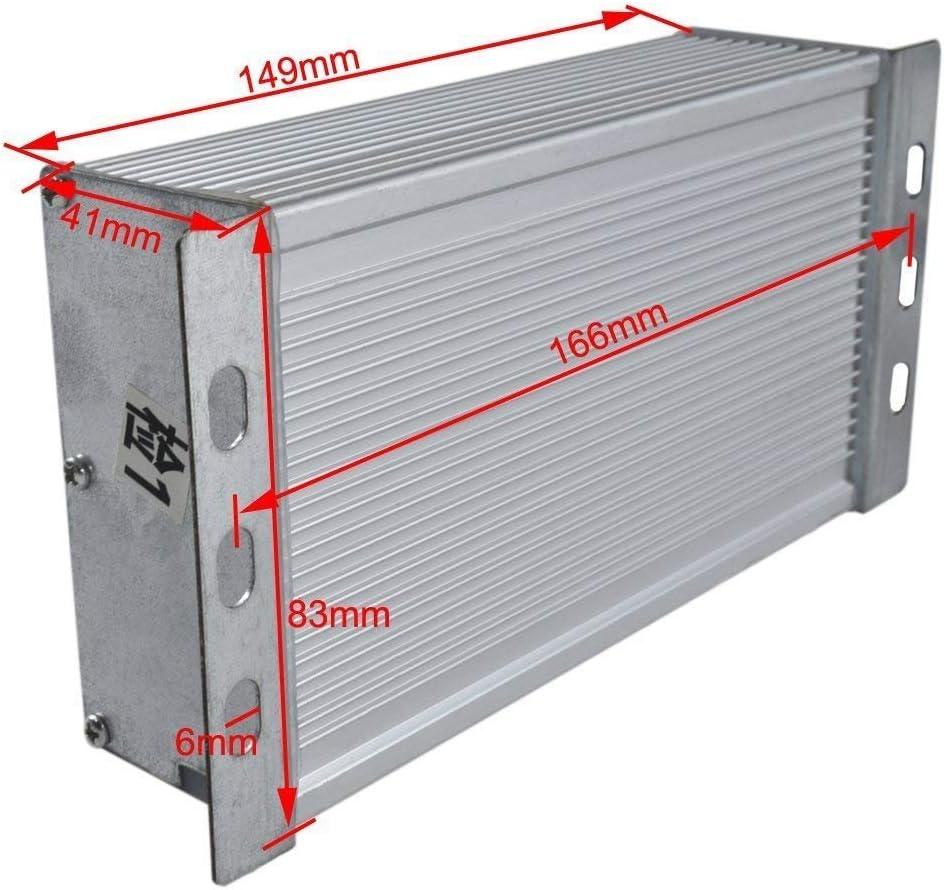
Figure 7: Dimensions of the motor controller. This image provides measurements for the controller unit, showing its length (166mm), width (83mm), and height (41mm), along with mounting bracket details.

Figure 8: Close-up view of the motor's 9-tooth sprocket. This image highlights the drive sprocket on the motor shaft, designed for a T8F chain, and includes some motor identification markings.
7. Warranty and Support
Information regarding product warranty and customer support was not provided in the available product data. For any warranty claims or technical assistance, please refer to the seller or manufacturer's official contact channels.


