1. Introduction
This manual provides essential information for the safe and efficient installation, operation, and maintenance of your Dieffematic Euro 230 M1 VDS E102 Gate Control Unit. This unit is designed to manage various gate automation systems, including sliding gates, barriers, and overhead doors, offering precise control and robust performance. Please read these instructions carefully before proceeding with installation or operation.
2. Safety Information
WARNING: Improper installation or use can lead to serious injury or damage. Always follow these safety guidelines:
- Installation must be performed by qualified personnel in compliance with local electrical and safety regulations.
- Disconnect power before performing any maintenance or installation procedures.
- Ensure all wiring connections are secure and properly insulated.
- Keep children and pets away from the gate area during operation.
- Do not attempt to repair the control unit yourself. Contact qualified service personnel.
- Ensure safety devices (e.g., photocells, safety edges) are correctly installed and functioning.
3. Product Overview
3.1. Key Features
- Versatile Control: Efficiently manages sliding gates, barriers, and overhead doors.
- Rapid Auto-learning: Integrated receiver with auto-learning capability, supporting both rolling code and fixed code for enhanced security and flexibility.
- Advanced Precision: Enables precise management of electric limit switches, offering slowdown functions and pedestrian opening for safe and controlled use.
- Robust Power Supply: Operates on 230VAC, ensuring stable and reliable performance for all automation systems, even under demanding conditions.
- Wide Compatibility: Designed for seamless integration with Dieffematic systems.
3.2. Components
The Dieffematic Euro 230 M1 VDS E102 control unit typically includes:
- Main Control Board
- Integrated Radio Receiver
- Terminal Blocks for Connections (Power, Motor, Safety Devices, Accessories)
- Enclosure (Housing the control board)
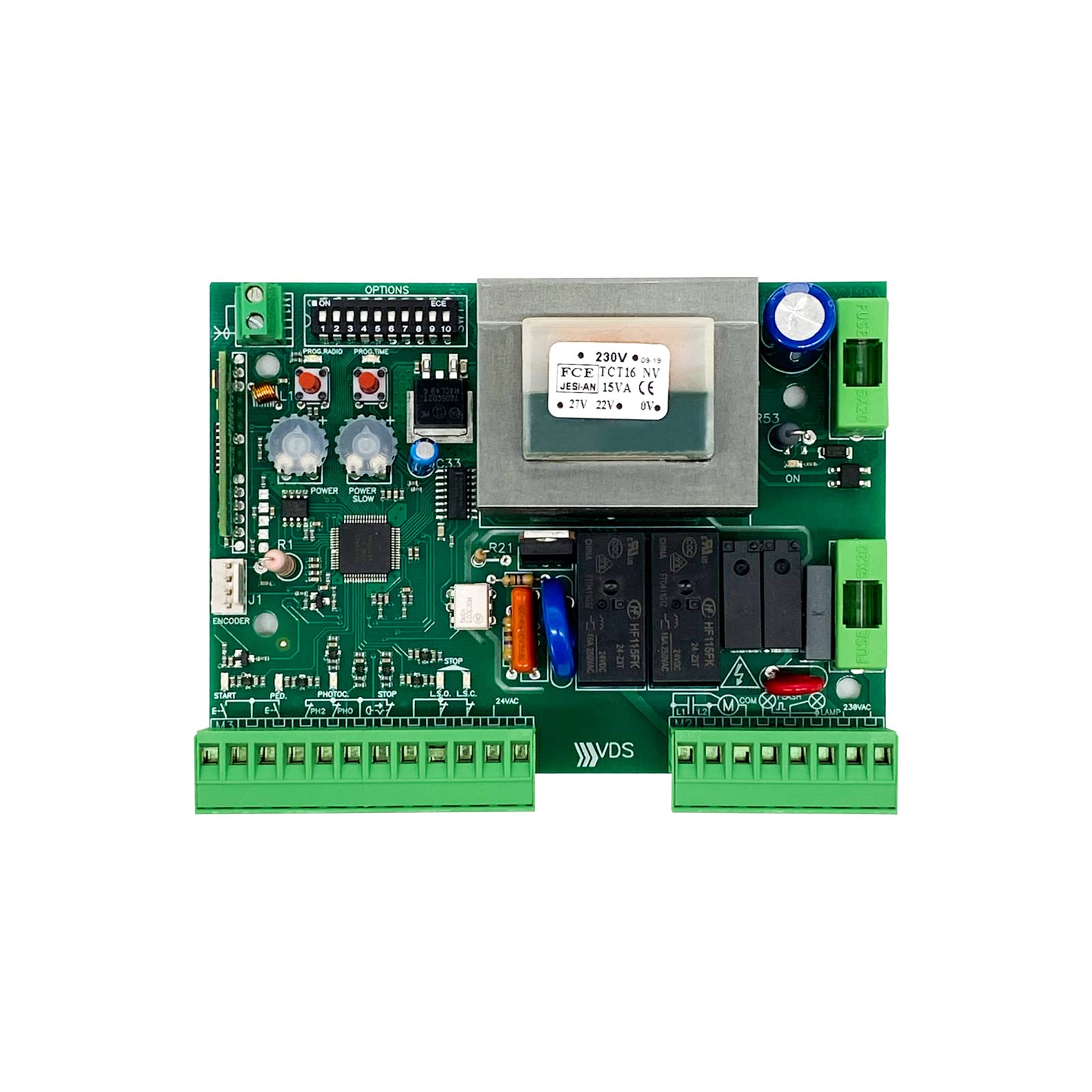
Figure 1: Dieffematic Euro 230 M1 VDS E102 Control Unit. This image shows the main control unit with its protective casing.
4. Setup and Installation
4.1. Mounting the Control Unit
- Choose a suitable location near the gate motor, protected from weather and direct sunlight.
- Mount the control unit securely using appropriate fasteners. Ensure it is level and easily accessible for wiring.
4.2. Electrical Connections
IMPORTANT: All electrical connections must be made with the main power supply disconnected. Refer to the wiring diagram for precise terminal identification.
- Main Power Supply: Connect the 230VAC power supply to the designated terminals (L, N, PE).
- Motor Connections: Connect the gate motor wires (common, open, close) to the motor output terminals.
- Safety Devices: Connect photocells, safety edges, and other safety devices to their respective input terminals.
- Accessories: Connect external command devices (e.g., push buttons, key switches) and flashing lights.
- Limit Switches: Connect electric limit switches for precise gate positioning.

Figure 2: Example Wiring Diagram. This diagram illustrates typical connections for power, motor, and safety accessories. Consult the specific diagram provided with your unit.
4.3. Initial Configuration and Auto-learning
- After all connections are made, restore power to the unit.
- Initiate the auto-learning procedure as described in the unit's specific programming guide. This typically involves pressing a programming button and allowing the gate to complete a full open and close cycle to learn its travel limits.
- Program remote controls: Follow the instructions to pair your remote controls with the integrated receiver. The unit supports both rolling code and fixed code transmitters.
- Adjust parameters: Set desired slowdown points, pedestrian opening width, and other operational parameters using the control board's interface or dip switches, as per the detailed programming manual.
5. Operating Instructions
5.1. Standard Operation
- Remote Control: Press the designated button on your remote control to open or close the gate. A second press during operation will typically stop the gate. A third press will reverse its direction.
- External Push Button: If connected, pressing the external push button will cycle the gate (open-stop-close-stop).
5.2. Pedestrian Opening
If configured, a specific button on your remote control or an external input can activate the pedestrian opening function, opening the gate partially for foot traffic.
5.3. Manual Release
In case of power failure or malfunction, the gate can be operated manually using the manual release mechanism on the gate motor. Refer to your gate motor's manual for specific instructions on how to engage the manual release.
6. Maintenance
Regular maintenance ensures the longevity and safe operation of your gate automation system.
- Monthly:
- Check the functionality of all safety devices (photocells, safety edges).
- Inspect the gate's movement for any obstructions or unusual noises.
- Every 6 Months:
- Inspect all wiring for signs of wear or damage.
- Clean the control unit enclosure and ensure ventilation openings are clear.
- Verify that all mounting screws are tight.
- Annual Professional Check: It is recommended to have a qualified technician inspect the entire gate automation system annually.
7. Troubleshooting
Before contacting technical support, review the following common issues and solutions:
| Problem | Possible Cause | Solution |
|---|---|---|
| Gate does not respond to remote control. |
|
|
| Gate opens but does not close. |
|
|
| Gate operates erratically. |
|
|
8. Specifications
- Model: Dieffematic Euro 230 M1 VDS E102
- Power Supply: 230VAC
- Motor Output: Designed for 230VAC gate motors
- Receiver Type: Integrated, auto-learning (rolling code / fixed code)
- Safety Inputs: Multiple inputs for photocells, safety edges, etc.
- Operating Temperature: Consult specific product datasheet for exact range.
- Protection Rating: Consult specific product datasheet.
9. Warranty and Support
Dieffematic products are covered by a standard manufacturer's warranty against defects in materials and workmanship. The specific terms and duration of the warranty may vary by region and product. Please retain your proof of purchase.
For technical assistance, troubleshooting beyond this manual, or warranty claims, please contact your authorized Dieffematic dealer or visit the official Dieffematic website for support contact information.


