1. Introduction
This manual provides essential information for the safe and effective installation, operation, and maintenance of the OMRON E3K-R10K4-NR Photocell Safety Sensor. Please read this manual thoroughly before using the product and keep it for future reference.
The OMRON E3K-R10K4-NR is a robust photoelectric sensor designed for industrial safety applications, detecting the presence or absence of objects within its sensing range. Its reliable performance contributes to enhanced operational safety and efficiency.
2. Safety Information
WARNING: Improper installation or use of this safety sensor can result in serious injury or death. Always follow all local and national safety regulations and standards.
- Ensure power is disconnected before installation or maintenance.
- Do not modify the sensor or its components.
- Only qualified personnel should install and service this device.
- Regularly inspect the sensor for damage or malfunction.
- This sensor is designed for specific applications; ensure it is suitable for your intended use.
3. Package Contents
Verify that all items are present and undamaged upon unpacking:
- OMRON E3K-R10K4-NR Photocell Safety Sensor unit
- Mounting bracket(s)
- Reflector (if applicable for retro-reflective models)
- Mounting hardware (screws, nuts, washers)
- Instruction Manual (this document)

Image 1: Contents of the OMRON E3K-R10K4-NR package, showing the sensor unit, a circular mounting ring, and an L-shaped bracket.
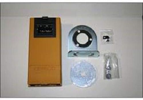
Image 2: Another view of the OMRON E3K-R10K4-NR sensor and its accessories, including the sensor, a mounting bracket, a reflector, and small bags of fasteners.
4. Setup and Installation
4.1 Mounting the Sensor
- Select a stable mounting location free from excessive vibration, dust, and moisture.
- Ensure the sensing area is clear of obstructions and the target object will pass reliably through the detection zone.
- Attach the mounting bracket securely to the desired surface using appropriate fasteners.
- Mount the sensor unit onto the bracket. Adjust its position to align with the target and, if applicable, the reflector.
- Tighten all mounting screws to prevent movement.
4.2 Wiring
Refer to the wiring diagram provided with your specific sensor model. Ensure all connections are secure and correctly polarized. Use appropriate cable glands and conduits to protect wiring from environmental factors.
- Power Supply: Connect to a stable power source within the specified voltage range.
- Output: Connect the sensor output to your control system (e.g., PLC, relay).
4.3 Alignment (for Retro-reflective/Through-beam models)
For models requiring a reflector or separate emitter/receiver, carefully align the sensor to ensure the light beam is correctly received. Most OMRON sensors include an indicator LED to assist with alignment; a steady green light typically indicates proper alignment.
5. Operating Instructions
5.1 Power On
After completing installation and wiring, apply power to the sensor. Observe the indicator LEDs for proper operation.
5.2 Detection Principle
The E3K-R10K4-NR operates on a photoelectric principle. Depending on the specific variant (e.g., retro-reflective, diffuse-reflective, through-beam), it detects objects by sensing changes in the emitted light beam. When an object enters the detection zone, the sensor's output changes state, signaling its presence to the connected control system.
5.3 Sensitivity Adjustment (if applicable)
Some models may feature a sensitivity adjuster. If present, use a small screwdriver to fine-tune the detection sensitivity according to your application's requirements. Test the detection with your target object to ensure reliable operation.
6. Maintenance
Regular maintenance ensures optimal performance and longevity of your sensor.
- Cleaning: Periodically clean the sensor lens and reflector (if used) with a soft, dry cloth. Avoid abrasive cleaners or solvents.
- Inspection: Check for any physical damage, loose wiring, or corrosion.
- Alignment Check: Verify that the sensor and reflector (if applicable) remain properly aligned.
- Functionality Test: Regularly test the sensor's detection capability with a known target object.
If any issues are detected, refer to the Troubleshooting section or contact OMRON support.
7. Troubleshooting
| Problem | Possible Cause | Solution |
|---|---|---|
| Sensor not detecting objects. |
|
|
| Sensor detects continuously (always ON/OFF). |
|
|
| Intermittent detection. |
|
|
8. Specifications
- Model: E3K-R10K4-NR
- Manufacturer: OMRON
- Type: Photocell Safety Sensor
- ASIN: B07JK8DNZY
- Date First Available: February 5, 2019
- Note: For detailed electrical and performance specifications, refer to the product datasheet provided by OMRON.
9. Warranty and Support
OMRON products are manufactured to high standards and are typically covered by a standard manufacturer's warranty against defects in materials and workmanship. For specific warranty terms and conditions, please refer to the warranty card included with your product or visit the official OMRON website.
For technical support, service, or replacement parts, please contact OMRON customer service or your authorized OMRON distributor. Have your model number (E3K-R10K4-NR) and purchase date ready when contacting support.
OMRON Official Website: www.omron.com