Introduction
This service manual provides detailed instructions for the maintenance, repair, and overhaul of Ford 850 series tractors manufactured between 1954 and 1957. It covers various systems and components, offering step-by-step procedures, diagrams, and specifications to assist in proper servicing. This document is intended for qualified technicians and individuals with mechanical aptitude.
Always refer to the specific sections for detailed information on engine, transmission, hydraulics, and other critical systems. Prioritize safety and use appropriate tools and personal protective equipment when performing any service procedures.
General Safety Information
Always observe the following safety precautions when working on the tractor:
- Ensure the tractor is parked on a level surface, the engine is off, and the parking brake is engaged before beginning any work.
- Disconnect the battery to prevent accidental starting or electrical shorts.
- Use appropriate lifting equipment and stands when working under the tractor.
- Wear safety glasses, gloves, and other personal protective equipment as required.
- Be aware of hot surfaces, sharp edges, and pressurized systems.
- Keep the work area clean and well-lit.
Engine Removal and Installation Procedures
This section outlines the procedure for removing and installing the engine for various Ford 850 tractor series. Careful attention to detail is required to ensure proper function and safety during these critical operations.
Series 1501 Engine Removal
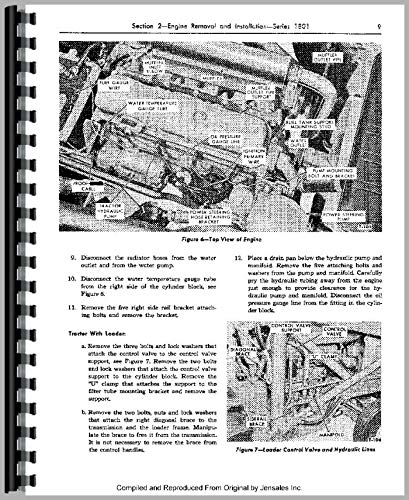
Figure 6: Top View of Engine. This image illustrates the various components of the engine from a top-down perspective, including the radiator hose, water outlet, water pump, fuel tank support, and other critical parts, with labels indicating their positions for removal.
- Disconnect the radiator hoses from the water outlet and from the water pump.
- Disconnect the water temperature gauge tube from the right side of the cylinder block.
- Remove the five right side rail bracket attaching bolts and remove the bracket.
- Place a drain pan below the hydraulic pump and manifold. Remove the five attaching bolts and washers from the pump and manifold. Carefully pry the hydraulic pump clear from the engine, taking care not to damage components.
- Disconnect the oil pressure gauge line from the fitting in the cylinder block.
Tractor With Loader (Additional Steps)
For tractors equipped with a loader, the following additional steps are required:
- Remove the three bolts and lock washers that attach the control valve to the control valve support.
- Remove the two bolts and lock washers that attach the control valve support to the cylinder block.
- Remove the two clamps that attach the support to the filter tube mounting bracket and remove the support.
- Remove the two bolts, nuts, and lock washers that attach the right diagonal brace to the transmission and the loader frame. Manipulate the brace to free it from the transmission. It is not necessary to remove the brace from the control handles.
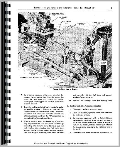
Figure 3: Right Side of Engine. This image provides a view of the engine from the right side, highlighting components such as the power steering pump, hydraulic pump manifold, and radiator hose, with labels for identification during removal and installation.
Engine Maintenance and Inspection
This section details the inspection, disassembly, and cleaning procedures for critical engine components, including rocker shaft assemblies and cylinder head flatness checks.
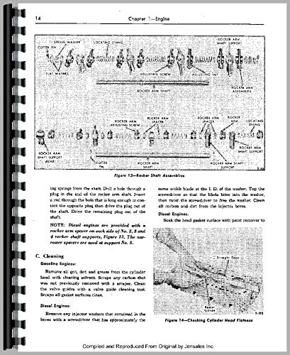
Figure 12: Rocker Shaft Assemblies. This diagram illustrates the exploded view of the rocker arm shaft components, including springs, flat washers, rocker arms, and adjusting screws, showing their correct assembly order. Figure 14: Checking Cylinder Head Flatness. This image demonstrates the method for checking the flatness of the cylinder head using a straight edge and feeler gauge, crucial for proper engine sealing.
Rocker Shaft Disassembly and Inspection
To disassemble the rocker shaft for inspection and service:
- Remove the cotter pins and flat washers from the shaft ends.
- Carefully slide the rocker arms and springs off the shaft, noting their original positions.
- Inspect all components (rocker arms, shaft, springs, bushings) for signs of wear, scoring, cracks, or deformation. Replace any worn or damaged parts.
Component Cleaning Procedures
Proper cleaning is essential for engine longevity and reliable operation.
Gasoline Engine Components
- Thoroughly remove all dirt, grit, and grease from the cylinder head using an appropriate cleaning solvent.
- Scrape any carbon deposits that were not previously removed with a suitable scraper.
- Clean the valve guides using a specialized valve guide cleaning tool.
- Ensure all gasket surfaces are scraped clean and free of old gasket material.
Diesel Engine Components
- Remove any injector washers that may have remained in the bores using a small screwdriver or pick.
- Soak the head gasket surface with paint remover to effectively loosen and remove any stubborn residue.
Troubleshooting Common Issues
This manual serves as a primary resource for diagnosing and resolving mechanical issues. While specific troubleshooting flowcharts are extensive and found throughout the manual's chapters, general principles include:
- Symptom Identification: Clearly identify the symptoms the tractor is exhibiting.
- System Isolation: Determine which system (engine, transmission, hydraulics, electrical) is most likely affected.
- Component Inspection: Visually inspect relevant components for obvious damage, leaks, or loose connections.
- Testing: Perform specific tests as outlined in the manual for the suspected component or system.
- Correction: Follow the repair procedures detailed in the relevant sections of this manual to correct the identified fault.
Specifications
This section provides key specifications for the Ford 850 Tractor Service Manual itself, as well as general information relevant to the product.
- ASIN: B07J9T4832
- Publisher: Jensales
- Language: English
- Manual Dimensions: 12 x 10 x 3 inches
Warranty and Support
Information regarding specific product warranties or direct technical support for the Ford 850 tractor is beyond the scope of this service manual. For inquiries related to the manual's content, potential errata, or purchasing additional copies, please contact the publisher, Jensales, directly. For tractor-specific warranty or support, please refer to original documentation or authorized Ford service centers from the period of manufacture.