Introduction
This manual provides detailed service and repair procedures for the Clark 28000 Powershift Transmission, specifically the HR Model-3 Speed. It is designed to assist technicians and experienced individuals in performing accurate maintenance, troubleshooting, and overhaul operations to ensure the optimal performance and longevity of the transmission.
How the Units Operate
This section provides an overview of the operational principles of the Clark 28000 Powershift Transmission. Understanding these principles is fundamental before proceeding with any service or repair work.
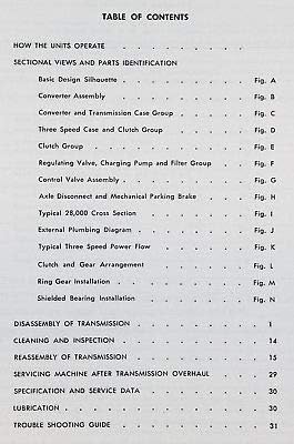
Image: A page from the manual showing the Table of Contents, which outlines the various sections including "HOW THE UNITS OPERATE".
Sectional Views and Parts Identification
Detailed diagrams and illustrations are provided to help identify various components and understand their arrangement within the transmission. Each figure provides a visual reference for specific assemblies.
Basic Design Silhouette (Figure A)
Figure A illustrates the fundamental design and overall silhouette of the transmission unit, providing a general overview of its structure.
Converter Assembly (Figure B)
Figure B details the components and assembly of the torque converter unit. This includes an exploded view for clear identification of all parts.
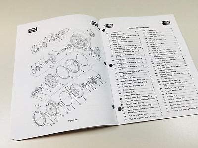
Image: A manual page featuring an exploded diagram labeled "Figure B", illustrating the converter assembly and an extensive list of numbered parts for identification.
Converter and Transmission Case Group (Figure C)
Figure C provides an exploded view and identification of parts within the converter and main transmission case group, showing how these major components integrate.

Image: A manual page displaying various transmission components and assembly steps, labeled "AUTOMATIC DIVISION", which may correspond to the converter and transmission case group.
Three Speed Case and Clutch Group (Figure D)
Figure D illustrates the components of the three-speed case and its associated clutch group, detailing their arrangement and interaction.
Clutch Group (Figure E)
Figure E provides detailed views and part identification for the various clutch components within the transmission, crucial for understanding power transfer.
Regulating Valve, Charging Pump and Filter Group (Figure F)
Figure F illustrates the assembly and individual parts of the regulating valve, charging pump, and filter group, essential for hydraulic control and lubrication within the transmission system.
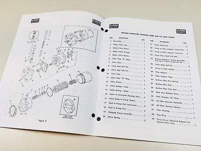
Image: A manual page displaying an exploded diagram labeled "Figure F" for the "PRESSURE REGULATOR, CHARGING PUMP AND OIL FILTER GROUP", accompanied by a comprehensive parts list.
Control Valve Assembly (Figure G)
Figure G details the components and function of the control valve assembly, which manages fluid flow for gear engagement and disengagement.
Axle Disconnect and Mechanical Parking Brake (Figure H)
Figure H provides diagrams and information regarding the axle disconnect mechanism and the mechanical parking brake system, outlining their construction and operation.
Typical 28000 Cross Section (Figure I)
Figure I presents a cross-sectional view of the entire 28000 transmission, showing the internal arrangement of major components and their spatial relationships.
External Plumbing Diagram (Figure J)
Figure J illustrates the external hydraulic plumbing connections and routes for the transmission system, vital for understanding fluid circulation.
Typical Three Speed Power Flow (Figure K)
Figure K explains the power flow paths through the three-speed transmission in different gear selections, demonstrating how power is transmitted.
Clutch and Gear Arrangement (Figure L)
Figure L details the specific arrangement of clutches and gears within the transmission for various speed ratios, showing their mechanical interconnections.
Ring Gear Installation (Figure M)
Figure M provides instructions and diagrams for the correct installation of the ring gear, ensuring proper meshing and function.
Shielded Bearing Installation (Figure N)
Figure N outlines the proper procedure for installing shielded bearings within the transmission assembly, highlighting critical steps for correct fitment.

Image: A manual page displaying "SHIELDED BEARING INSTALLATION" (Fig. N) with detailed diagrams, alongside an assembly diagram for "IMPELLER HUB, TURBINE HUB AND BACKING RING WITH SPECIAL SCREWS" (Fig. D).
Disassembly of Transmission
This section provides step-by-step instructions for the safe and proper disassembly of the Clark 28000 Powershift Transmission. Adherence to these procedures is critical to prevent damage to components and ensure successful reassembly.

Image: A manual page illustrating "DISASSEMBLY OF LOW CLUTCH HOUSING" with multiple photographic figures demonstrating the process.
Cleaning and Inspection
After disassembly, all components must be thoroughly cleaned and inspected for wear, damage, or defects. This section details the cleaning methods and inspection criteria for various parts to determine their reusability or the need for replacement.
Reassembly of Transmission
This section guides the user through the reassembly process of the transmission, ensuring all components are installed correctly and to specified tolerances. Proper torque values and assembly sequences are critical for reliable operation.
Image: A manual page illustrating "REASSEMBLY" steps with multiple photographic figures demonstrating the process, including installation of bearings and clutch components.
Servicing Machine After Transmission Overhaul
After the transmission has been overhauled and reinstalled, specific procedures must be followed to ensure proper integration and initial operation within the machine. This includes fluid filling, system bleeding, and initial functional checks.
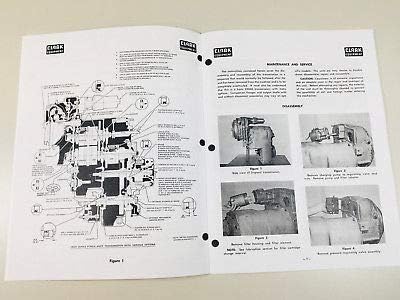
Image: A manual page titled "MAINTENANCE AND SERVICE" which includes diagrams and images related to disassembly and servicing, relevant to post-overhaul procedures.
Specification and Service Data
This section provides critical technical specifications, clearances, tolerances, and other essential data required for accurate service and repair. Refer to these specifications for all measurement and adjustment procedures.
Lubrication
Proper lubrication is vital for the longevity and performance of the transmission. This section outlines recommended lubricant types, capacities, and intervals for fluid changes and checks.
Troubleshooting Guide
This guide assists in diagnosing common issues and malfunctions that may occur with the Clark 28000 Powershift Transmission. It provides symptoms, possible causes, and recommended corrective actions to resolve problems efficiently.
Common Transmission Issues| Symptom | Possible Cause | Corrective Action |
|---|
| No power in any gear | Low fluid level, clogged filter, pump failure | Check fluid, replace filter, inspect pump |
| Delayed engagement | Worn clutch plates, low line pressure | Inspect clutches, check pressure regulator |
| Overheating | Insufficient cooling, slipping clutches, restricted cooler lines | Check cooler, inspect clutches, clear lines |