Hex Technology HX4-06038
The Cube Kore User Manual
Model: HX4-06038 | Brand: Hex Technology
1. Introduction
The Hex Technology Cube Kore is a specialized carrier board designed to streamline the integration of the Pixhawk 2.1 Cube (sold separately) into multirotor applications. It consolidates all necessary wiring and connections, simplifying the build process for advanced drone systems. The Kore board provides robust power distribution, signal management, and various connectivity options for peripheral components, ensuring reliable operation and expandability.
2. Key Features
- All-in-one Design: Integrates Pixhawk 2.1 carrier and power distribution for simplified multirotor builds.
- High Power Capacity: Supports up to 12-cell Lithium battery (50.4V) with 140A continuous current and 280A surge capability.
- Integrated Signal Outputs: Provides signal outputs for up to 8-arm drone configurations.
- Built-in Sensing: Features integrated voltage and current sensing for precise power monitoring.
- Redundant Power: Includes redundant power supplies for flight-critical components, enhancing reliability.
- Payload Connectors: Equipped with resettable fuses for 5V, 12V, and direct battery power to payloads.
- Indicator Lights & Buzzer: Good power and error indicator lights, plus a built-in buzzer with volume control.
- PWM Voltage Selection: Easily accessible PWM voltage level selector (3.3V or 5V).
- Ground Bounce Resistance: Designed to be resistant to ground bounce on PWM signals.
- Standard Compatibility: Connector-compatible with standard ProfiCNC carrier boards.
- Debugging Ports: Includes connector ports for debugging IO and FMU processors.
3. Package Contents
Verify that all items listed below are present in your package. The Pixhawk 2.1 Cube is NOT included with the Kore carrier board and must be purchased separately.

Figure 3.1: Contents of the Cube Kore package.
- 1x Kore Carrier Board: The main board for Pixhawk 2.1 Cube integration.
- 1x I2C Board: For I2C peripheral expansion.
- 1x Nylon Tube Set: For mounting and securing components.
- 1x Micro USB Cable: For connecting to a computer.
- 1x XT60 Power Cable: For main battery connection.
- 1x Vbat Power Cable: For battery voltage sensing.
- 1x 12V/2A Power Cable: For 12V power output.
- 1x 5V/1.5A Power Cable: For 5V power output.
- 1x CAN Cable: For CAN bus communication.
- 1x I2C Cable: For I2C communication.
- 1x Telem Cable: For telemetry connection.
- 1x GPS1 Cable: For primary GPS connection.
- 1x GPS2 Cable: For secondary GPS connection.
4. Setup Guide
This section outlines the general steps for setting up your Cube Kore carrier board. Ensure you have the Pixhawk 2.1 Cube and all necessary multirotor components before proceeding.
4.1. Board Overview
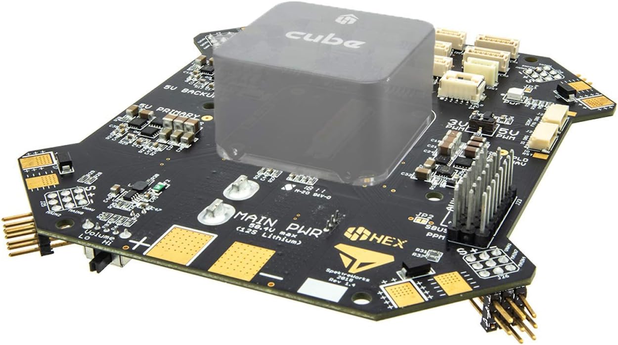
Figure 4.1: Cube Kore Carrier Board (top view with Cube placeholder).
The Cube Kore board is designed for easy integration. The central square area is where the Pixhawk 2.1 Cube module securely mounts. Surrounding this area are various connectors for ESCs, power, and peripherals.

Figure 4.2: Cube Kore Carrier Board (bottom view).
The bottom of the board houses the built-in buzzer, control buttons, and additional components for power management and signal processing.
4.2. Mounting the Pixhawk 2.1 Cube
- Carefully align the Pixhawk 2.1 Cube with the central connector on the Kore carrier board.
- Gently press the Cube down until it is firmly seated. Ensure all pins are correctly aligned to prevent damage.
- Secure the Cube using the provided mounting hardware (if applicable, typically part of the Cube package).
4.3. Connecting ESCs and Motors
The Kore board features dedicated power and signal pads at each corner for connecting Electronic Speed Controllers (ESCs). These are designed for multirotor configurations up to 8 arms.
- Connect the power leads of each ESC to the corresponding power pads (positive and negative) on the Kore board. Ensure correct polarity.
- Connect the signal wire of each ESC to the designated PWM signal pin for that motor output. Refer to your flight controller's documentation for specific motor assignments.
- Connect the motor wires to the ESCs according to your motor's rotation direction requirements.
4.4. Power Supply Connection
The Kore board supports up to 12-cell Lithium batteries (50.4V) and handles high continuous and surge currents.
- Connect your main flight battery (e.g., via XT60 connector) to the designated main power input on the Kore board.
- Ensure the battery voltage is within the supported range (up to 50.4V).
4.5. Peripheral Connections
The Kore board provides various ports for connecting essential peripherals:
- GPS/Compass: Use the provided GPS cables to connect your GPS and compass modules to the designated ports (GPS1, GPS2).
- Telemetry: Connect your telemetry radio using the Telem cable.
- I2C: Use the I2C cable and I2C board for connecting I2C peripherals like external compasses or airspeed sensors.
- CAN: Connect CAN bus devices using the CAN cable.
- Payload Power: Utilize the 5V, 12V, and direct battery payload power connectors with resettable fuses for cameras, gimbals, or other accessories.
- USB: Connect the Micro USB cable to the board for configuration and firmware updates via your flight controller software.

Figure 4.3: Detailed view of Cube Kore connections.
For a comprehensive understanding of the CubePilot ecosystem and how the Kore board integrates, refer to the official CubePilot documentation and diagrams.
5. Operating Instructions
The Cube Kore board acts as a power distribution and signal routing hub for the Pixhawk 2.1 Cube. Its operation is largely dependent on the configuration and firmware of the Pixhawk Cube itself.
5.1. Powering On
- Ensure all connections are secure and correct.
- Connect the main flight battery to the Kore board.
- Observe the indicator lights on the Kore board and the Pixhawk Cube. A solid green light typically indicates stable power.
- Listen for the initialization tones from the built-in buzzer, indicating the Pixhawk Cube is booting up.
5.2. System Status Indicators
- Power Indicator: A dedicated LED indicates the status of the main power supply.
- Error Indicator: An LED will illuminate or flash to indicate system errors or warnings. Consult the Pixhawk Cube documentation for specific error codes.
- Buzzer: Provides audible feedback for system status, arming/disarming, and warnings. The volume can be adjusted.
5.3. PWM Voltage Selection
The Kore board allows selection of PWM signal voltage (3.3V or 5V) to match your ESCs or other PWM-controlled devices. Refer to the board's markings or the official documentation for the location of the voltage selector jumper or switch.
Caution: Ensure the selected voltage matches the requirements of your connected devices to prevent damage.
6. Maintenance
Proper maintenance ensures the longevity and reliability of your Cube Kore board.
- Regular Inspection: Periodically inspect the board for any signs of physical damage, loose connections, or corrosion.
- Cleaning: Keep the board clean and free from dust, dirt, and moisture. Use a soft, dry brush or compressed air for cleaning. Avoid using liquids or solvents.
- Storage: When not in use, store the board in a dry, anti-static environment, away from extreme temperatures.
- Connection Integrity: Ensure all cables and connectors are securely seated and free from strain.
7. Troubleshooting
This section provides basic troubleshooting steps for common issues. For more complex problems, refer to the Pixhawk Cube documentation or contact Hex Technology support.
| Problem | Possible Cause | Solution |
|---|---|---|
| No power to Pixhawk Cube/peripherals. |
|
|
| Buzzer not sounding or sounding incorrectly. |
|
|
| Peripheral (e.g., GPS, Telemetry) not detected. |
|
|
8. Technical Specifications
| Feature | Specification |
|---|---|
| Model Number | HX4-06038 |
| Supported Battery Voltage | Up to 12-cell Lithium (50.4V max) |
| Continuous Current | 140A |
| Surge Current | 280A |
| PWM Outputs | Up to 8-arm configurations |
| PWM Voltage Selector | 3.3V or 5V |
| Integrated Sensors | Voltage and Current Sense |
| Payload Power Outputs | 5V, 12V, Direct Battery (with resettable fuses) |
| Dimensions (Package) | 16.51 x 14.48 x 4.83 cm |
| Weight (Package) | 159 g |
9. Warranty and Support
For specific warranty information regarding your Cube Kore board, please refer to the documentation provided at the time of purchase or visit the official Hex Technology website. Warranty terms may vary based on region and retailer.
For technical support, troubleshooting assistance beyond this manual, or inquiries about product functionality, please contact Hex Technology directly:
- Manufacturer: Hex Technology
- Website: www.hex.aero (Please check for the most current contact information)
- Online Resources: Many common questions and detailed guides can be found on the CubePilot official documentation website.
When contacting support, please have your product model number (HX4-06038) and a detailed description of the issue ready.