1. Introduction
The J-Tech Digital Wireless HDMI Extender Kit (JTECH-WEX200V3) is designed to wirelessly extend HDMI audio and video signals. This kit includes a transmitter (TX) and a receiver (RX) unit, enabling high-definition video transmission over distances up to 200 feet (61 meters) through common obstructions like interior drywall.
Key features include:
- High Definition Video Output: Supports resolutions up to 1080P at 60Hz.
- Extended Range: Transmits signals up to 200 feet (61 meters) through walls and ceilings.
- Multi-Receiver Support: One transmitter can pair with up to two receivers simultaneously.
- Low Latency: Achieves a latency time of less than 0.3 seconds, suitable for video playback.
- IR Passthrough: Allows control of the source device from the display location using an IR remote.
- Customizable SSID & Channel: Enables multiple extender sets to operate in the same environment without interference.

Figure 1.1: J-Tech Digital Wireless HDMI Extender Kit.
2. Package Contents
Verify that all items listed below are included in your package:

Figure 2.1: Contents of the JTECH-WEX200V3 package.
- 1x JTECH-WEX200V3 Transmitter (TX) Unit
- 1x JTECH-WEX200V3 Receiver (RX) Unit
- 2x DC 12V/1A Power Adapters
- 1x IR Blaster Cable
- 1x IR Receiver Cable
- 1x User Manual
3. Product Overview
Familiarize yourself with the components and interfaces of the transmitter and receiver units.

Figure 3.1: Interface layout of the Transmitter and Receiver.
3.1 Transmitter (TX) Unit

Figure 3.2: Transmitter Unit details.
- DC 12V: Power input port.
- HDMI Input: Connects to your HDMI source device.
- HDMI Loop Out: Connects to a local display for monitoring the source signal.
- IR Out: Connects to the IR Blaster cable to control the source device.
- Reset/Channel Button: Short press to show Channel ID info; press and hold for 3 seconds to change Channel ID.
3.2 Receiver (RX) Unit

Figure 3.3: Receiver Unit details.
- DC 12V: Power input port.
- HDMI Output: Connects to your HDMI display device.
- IR In: Connects to the IR Receiver cable to receive IR signals from your remote.
- Reset Button: Resets the receiver unit.
4. Setup Instructions
Follow these steps to set up your J-Tech Digital Wireless HDMI Extender.
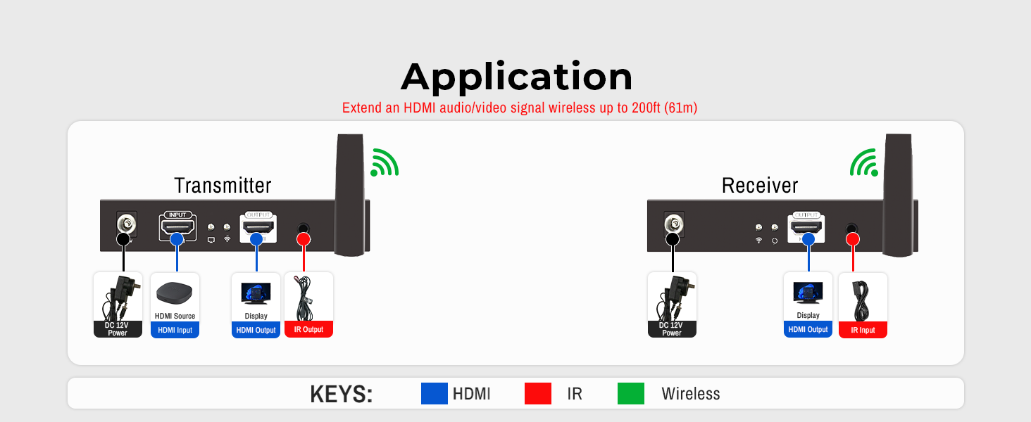
Figure 4.1: General application diagram.
4.1 One-to-One Connection
This configuration allows one source device to transmit its signal wirelessly to one display.

Figure 4.2: One-to-One Connection setup.
- Connect your HDMI source (e.g., Blu-ray player, cable box) to the HDMI Input port on the Transmitter (TX) unit.
- (Optional) Connect a local display to the HDMI Loop Out port on the TX unit if you wish to monitor the source signal locally.
- Connect your HDMI display (e.g., TV, projector) to the HDMI Output port on the Receiver (RX) unit.
- Connect the IR Blaster cable to the IR Out port on the TX unit and position the IR emitter near the IR sensor of your source device.
- Connect the IR Receiver cable to the IR In port on the RX unit and position the IR receiver in a location where it can receive signals from your remote control.
- Connect the provided 12V/1A power adapters to both the TX and RX units and plug them into power outlets.
- Ensure both units are powered on. The system should automatically establish a wireless connection and display the source content on the connected display(s).
4.2 One-to-Two Connection
This configuration allows one source device to transmit its signal wirelessly to two displays simultaneously.

Figure 4.3: One-to-Two Connection setup.
- Follow steps 1, 2, 4, and 6 from the One-to-One Connection setup for the Transmitter (TX) unit.
- For the two Receiver (RX) units, connect each to a separate HDMI display via their HDMI Output ports.
- Connect an IR Receiver cable to the IR In port on each RX unit and position them appropriately.
- Connect the power adapters to both RX units.
- Ensure all units are powered on. The TX unit will broadcast the signal to both RX units, displaying the content on both connected displays.
4.3 Multiple Pair Operation
Up to four JTECH-WEX200V3 extender pairs can operate in the same environment without interference by customizing their SSID and 5GHz operating frequency.
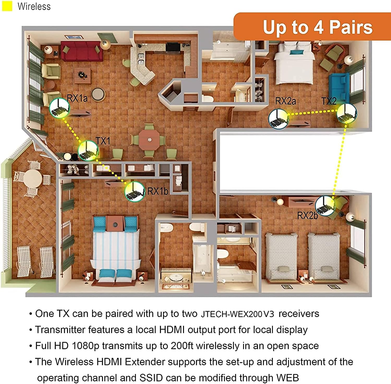
Figure 4.4: Example of multiple extender pairs in a single environment.
Refer to Section 5.2 for details on customizing SSID and Channel ID.
5. Operating Instructions
5.1 Wireless Transmission
Once connected and powered on, the transmitter and receiver units will automatically establish a wireless link. The system supports full HD 1080P video transmission with minimal latency, making it suitable for video playback and content sharing.
Video 5.1: Overview of the J-Tech Digital Wireless HDMI Extender's features and capabilities.
5.2 Customizing SSID and Channel ID
To prevent interference when using multiple extender sets, you can customize the SSID (network name) and 5GHz operating frequency of each pair.
- Connect a PC or mobile device to the extender's wireless network. The default SSID is typically "JTD_HDMI_Wireless_X" (where X is a number).
- Open a web browser and enter the default IP address (usually 192.168.1.10) to access the web interface.
- Log in using the default credentials (refer to the full user manual for specific details).
- Navigate to the wireless settings to change the SSID and select a different 5GHz channel. Save your changes.
- Alternatively, you can short press the Reset/Channel Button on the Transmitter to display the current Channel ID on the connected display. Press and hold the button for 3 seconds to cycle through available 5GHz wireless channels. Ensure both the TX and RX units are on the same channel for proper operation.
5.3 IR Passthrough
The IR passthrough feature allows you to control your HDMI source device (e.g., DVD player, set-top box) from the location of your display. Simply point your source device's remote control at the IR Receiver cable connected to the RX unit, and the signal will be transmitted back to the IR Blaster cable connected to the TX unit, controlling your source device.
6. Specifications
Technical specifications for the J-Tech Digital Wireless HDMI Extender JTECH-WEX200V3:
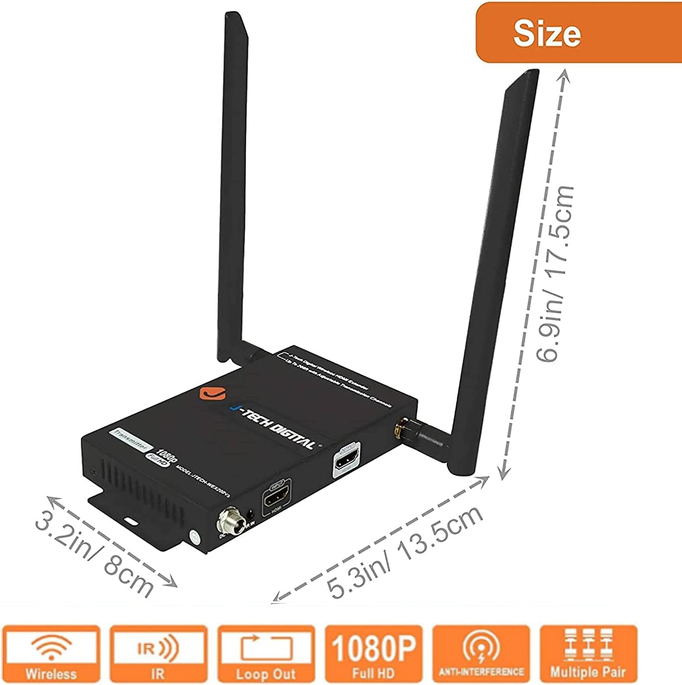
Figure 6.1: Product dimensions.
| Feature | Detail |
|---|---|
| Model Number | JTECH-WEX200V3 |
| Product Dimensions | 6.9 x 5.3 x 3.2 inches |
| Item Weight | 2.29 pounds |
| Brand | J-Tech Digital |
| Connectivity Technology | HDMI, Wireless |
| Compatible Devices | Personal Computer, various HDMI sources |
| Total HDMI Ports | 2 (1 Input, 1 Loop Out on TX; 1 Output on RX) |
| Audio Output Mode | Stereo, Surround |
| Surround Sound Channel Configuration | 5.1 |
| Video Encoding | H.264, MPEG-2 |
| Color | Black |
| Max Resolution | 1080P @ 60Hz |
| Transmission Range | Up to 200 feet (61 meters) |
| Latency | Less than 0.3 seconds |
7. Troubleshooting
If you encounter issues with your J-Tech Digital Wireless HDMI Extender, refer to the common problems and solutions below.
7.1 No Signal or Picture
- Check Power: Ensure both the Transmitter and Receiver units are properly powered on and their power indicator lights are illuminated.
- HDMI Connections: Verify that all HDMI cables are securely connected to both the source device, extender units, and display. Try re-seating the cables.
- Source Output: Confirm that your HDMI source device is outputting a signal and is set to a compatible resolution (up to 1080P).
- Display Input: Ensure your display is set to the correct HDMI input channel.
- Wireless Connection: Check the wireless status indicators on both units. If they are not linked, try power cycling both units.
7.2 Signal Interference or Dropping
- Obstructions: Reduce the number of physical obstructions (walls, furniture) between the transmitter and receiver. Concrete or thick walls can significantly reduce range.
- Distance: Ensure the units are within the recommended 200ft (61m) transmission range.
- Wireless Channel: Other 5GHz wireless devices (e.g., Wi-Fi routers, cordless phones) can cause interference. Try changing the operating channel of your extender using the web interface or the channel button on the TX unit (refer to Section 5.2).
- Power Cycle: If the signal drops frequently, try power cycling both the transmitter and receiver units.
7.3 IR Remote Control Not Working
- Cable Connection: Ensure the IR Blaster and IR Receiver cables are securely connected to their respective ports on the TX and RX units.
- IR Emitter/Receiver Placement: Verify that the IR emitter on the Blaster cable is directly aligned with the IR sensor on your source device. Ensure the IR receiver on the Receiver cable is positioned to clearly receive signals from your remote control.
- Remote Batteries: Check the batteries in your remote control.
8. Warranty and Support
All J-Tech Digital products come with a One-Year Manufacturer Warranty. Additionally, free lifetime technical support is available from our Customer Support Team based in Houston, Texas.
Support hours are Monday through Friday, 9 AM to 6 PM CST.
For contact information, please refer to the J-Tech Digital Seller Page on Amazon or visit the official J-Tech Digital website.

Figure 8.1: J-Tech Digital Customer Support.


