
1. Introduction
This user manual provides comprehensive instructions for the installation, operation, and maintenance of your NATIKA Backup/Front View Camera. Designed for versatility and durability, this camera offers enhanced visibility for various vehicle types, ensuring safer maneuvering and parking. Please read this manual thoroughly before installation and use to ensure proper functionality and longevity of your device.
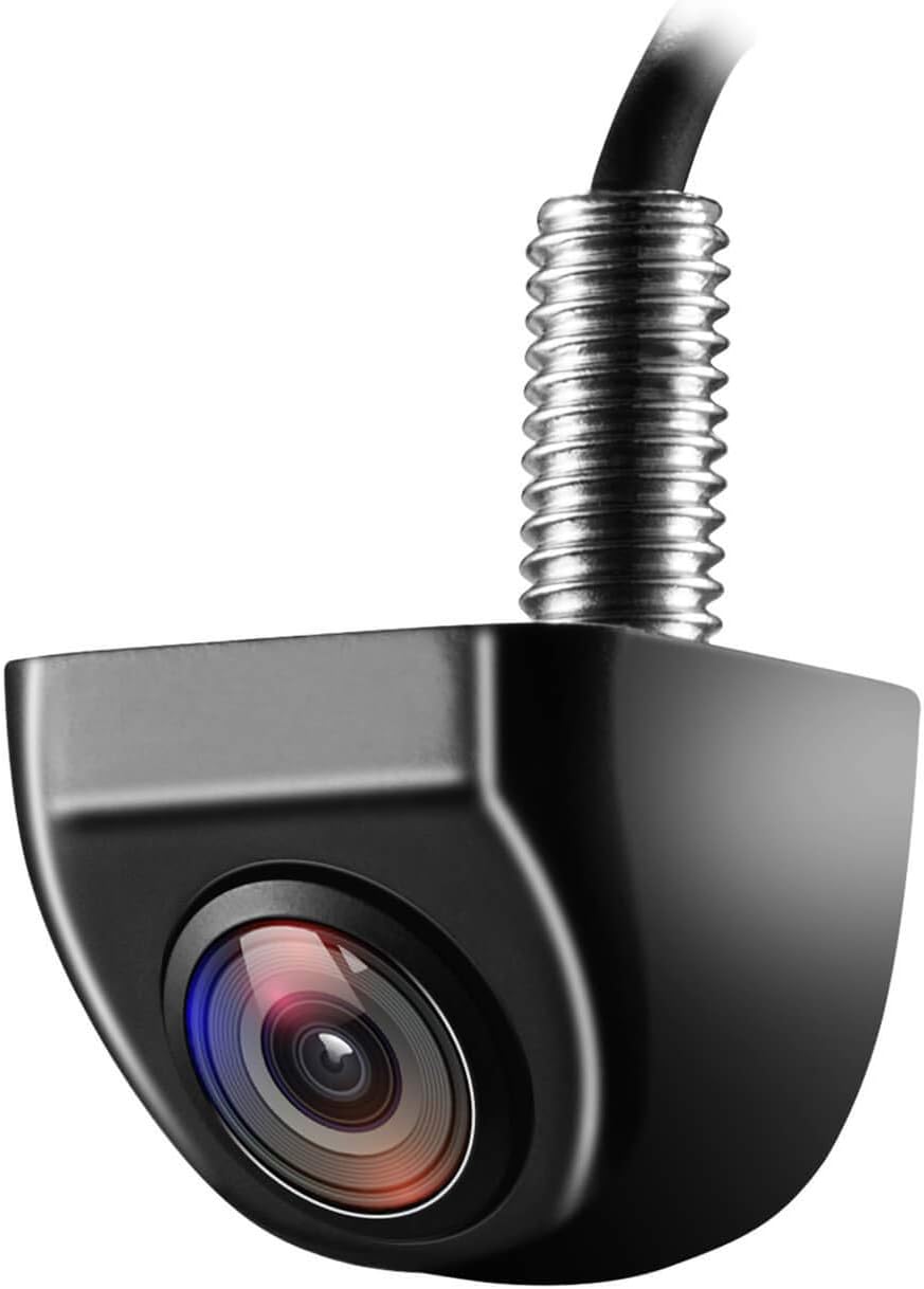
Figure 1: NATIKA Backup/Front View Camera (Black model shown)
2. Features
- IP69K Waterproof Rating: Designed with fully sealed glue filling craft, ensuring protection against water, fog, or mist.
- High-Definition Imaging: Features a latest HD 600TVL 1/2.7inch image sensor for clear visuals.
- Super Wide Viewing Angle: Horizontal 135-degree lens helps eliminate blind spots for safer parking and reversing.
- Durable Metal Housing: Small size and OEM style design with robust metal construction.
- Multifunctional Switching Loops: Allows switching between front view and rear view, and enables/disables guide lines. Supports vertical downward view for tailgate mounting.
- Wide Vehicle Compatibility: Compatible with most DC 12-24V vehicles, including Cars, Pickup Trucks, SUVs, RVs, and Vans.
- Excellent Low Light Performance: Operates effectively in low illumination levels down to 0.01 Lux.

Figure 2: IP69K Waterproof design for durability in various conditions.

Figure 3: Visual comparison highlighting superior resolution, low-light performance, and wider view angle.
3. What's in the Box
Verify that all components are present and in good condition upon opening the package:
- 1 x NATIKA Backup Camera
- 1 x 26ft/8M Extension Wire/Cable
- 1 x 304 Stainless Nut
- 1 x Double Tape
- 1 x Electrical Tape
- 3 x Gaskets (for view angle adjustment)
- 1 x Panel Remover
- 7 x Zip Ties
- 1 x User Manual (this document)
- 1 x Thanks Card
- 1 x NATIKA Gift Box

Figure 4: All items included in the NATIKA Backup Camera package.
4. Setup and Installation
Careful installation is crucial for optimal performance. Follow these steps:
4.1. Wire/Loop Control Configuration
The camera features small wires/loops (White, Green, and Purple) for customizable functionality:
- Purple Wire/Loop: Controls mounting style.
- Keep the purple wire/loop for hanging mounting (ideal for Sedans, SUVs).
- Cut the purple loop for sitting mounting (ideal for pickup trucks, RVs, and Vans).
- Green Wire/Loop: Controls guide lines.
- Keep the green wire/loop if you need the guide line.
- Cut the green loop if you do not need the guide line.
- White Wire/Loop: Controls view direction.
- Cut the white wire/loop for front view camera functionality.
- Keep the white wire/loop for rear view camera functionality.
- Front View without Guide Line: Cut both the white and green wires/loops.
- Side View Camera: Can only be installed on a horizontal surface (e.g., under left or right mirror), not a round, slant, or perpendicular surface.
- To look backward, keep the white wire/loop.
- To look forward, cut the white wire/loop.

Figure 5: Wire/Loop control for camera functionality (guide lines, mounting, view direction).
4.2. Mounting the Camera
Mount the camera on the desired panel. Ensure the wire is routed to the inside of the vehicle. DO NOT pinch the wire/cable when routing. Drill a hole if necessary to allow the wire to pass through without damage.

Figure 6: Examples of camera installation on different vehicle rear panels and tailgate handles.
4.3. Electrical Connections
- Connect the camera's male plug to the female connector of the extension wire/cable. Ensure the arrows on the connectors align and push the plug tightly.
- Apply electrical tape for the joint of the red power wires and RCA wires to ensure secure and insulated connections.
- Use zip ties to fasten the wire securely on your vehicle, preventing loose cables.
- If your head unit has a reverse triggering wire (normally pink), connect it with the extension wire's triggering wire (small short red wire next to the RCA/AV connector).
- Note: Monitor/LCD/Screen/Display/Radio are not included. If connecting to a FACTORY RADIO, you may need to separately order a suited Harness & Programmer to complete the installation, as different radios require specific components.
4.4. Adjusting View Angle (Optional)
To adjust the camera view angle, select one of the three suitable size gaskets/shims provided. Apply silicon to seal it if needed for additional protection.

Figure 7: Gaskets provided for adjusting the camera's view angle.
5. Operating Instructions
Once properly installed, the NATIKA camera will provide a clear view of your surroundings. The display will typically activate automatically when the vehicle is put into reverse, or when manually switched if configured for front/side view.
- Rear View Mode: When connected to the reverse light circuit, the camera automatically displays the rear view with or without guide lines (depending on green loop configuration) when shifting into reverse.
- Front View Mode: If configured for front view (white loop cut), the camera can be activated via your head unit's input selection or a dedicated switch (if installed).
- Guide Lines: The dynamic guide lines assist with parking by showing the projected path of your vehicle. These can be enabled or disabled during setup as described in Section 4.1.
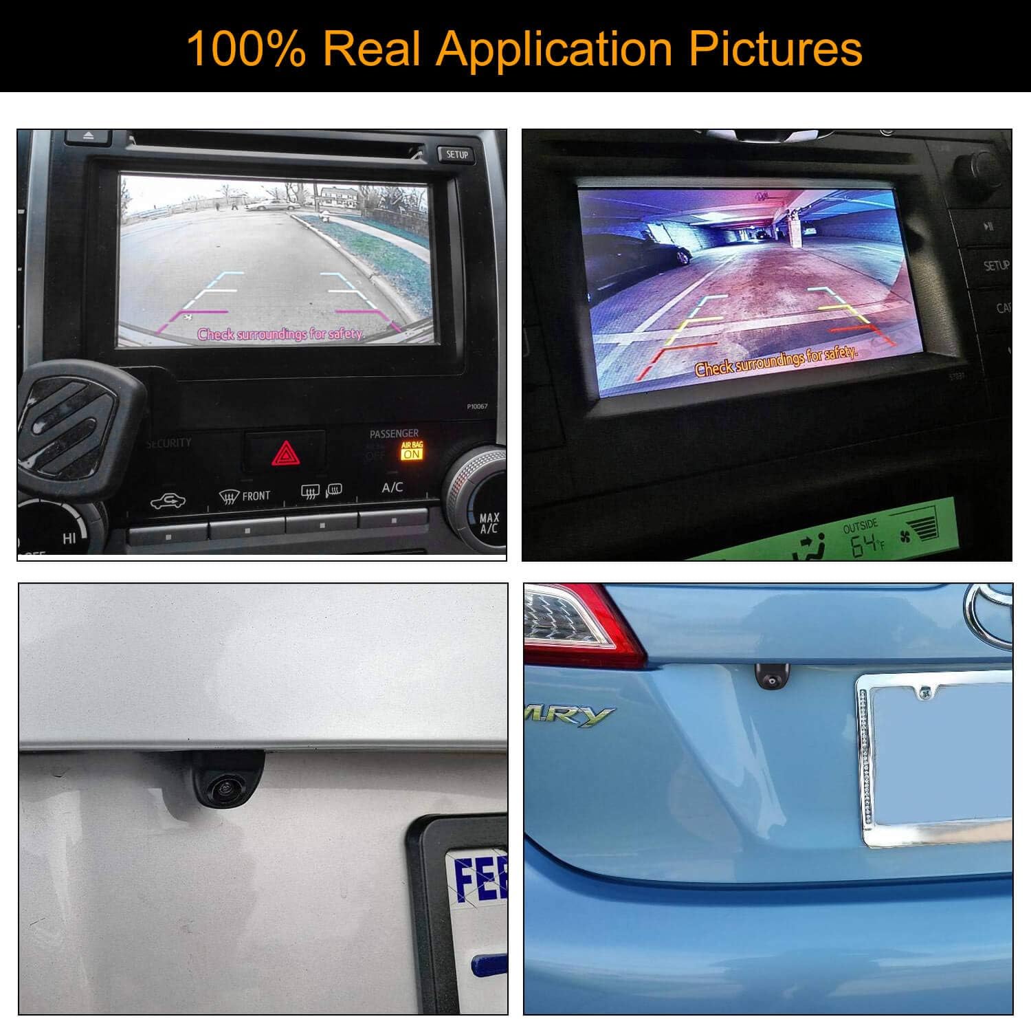
Figure 8: Examples of the camera's view on a vehicle's display, showing clear visibility and guide lines.
6. Maintenance
To ensure the longevity and optimal performance of your NATIKA camera, follow these maintenance guidelines:
- Clean the Lens: Regularly clean the camera lens with a soft, damp cloth to remove dirt, dust, or water spots that may obstruct the view. Avoid abrasive cleaners.
- Check Connections: Periodically inspect all wiring connections to ensure they are secure and free from corrosion or damage. Re-tape or re-secure any loose connections.
- Inspect Mounting: Verify that the camera remains securely mounted to prevent vibrations or misalignment that could affect image quality.
- Avoid Harsh Chemicals: Do not use strong chemical cleaners or solvents on the camera body or lens, as this may damage the materials or coatings.
7. Troubleshooting
If you encounter issues with your NATIKA camera, refer to the following common problems and solutions:
| Problem | Possible Cause | Solution |
|---|---|---|
| No image on screen |
|
|
| Blurry, flickering, or distorted image (horizontal/vertical strips) |
|
|
| Guide lines not appearing/disappearing | Incorrect green wire/loop configuration. | Refer to Section 4.1 "Wire/Loop Control Configuration" to ensure the green wire/loop is correctly configured (kept for ON, cut for OFF). |
| Camera view is mirrored or reversed | Incorrect white wire/loop configuration. | Refer to Section 4.1 "Wire/Loop Control Configuration" to ensure the white wire/loop is correctly configured (kept for rear view, cut for front view). |
8. Specifications
| Specification | Value |
|---|---|
| Brand | Natika |
| Model Number | backup camera WD-011 |
| Item Weight | 12 ounces |
| Product Dimensions | 1 x 1 x 0.78 inches (27mm x 27mm x 21mm) |
| Country of Origin | China |
| Lux Rating | 0.01 Lux |
| Compatible Devices | Sony, Alpine, JVC, Boss, Atoto, Jensen, Pyle, Podofo, CAMECHO stereos receivers, Kenwood, Pioneer receivers, Any head units with a female RCA connector |
| Installation Type | Vertical and horizontal Mount |
| Video Capture Resolution | 720p |
| Voltage | 12 Volts |
| Optical Sensor Technology | CMOS |
| Effective Still Resolution | 576 Pixels |
| Lens Type | Wide Angle |

Figure 9: Detailed dimensions of the NATIKA Backup Camera.
9. Warranty and Support
NATIKA is committed to customer satisfaction. Your NATIKA Backup/Front View Camera comes with:
- 24 Months Replacement Warranty: For peace of mind regarding product defects or malfunctions.
- Lifetime Support Guarantee: Ongoing assistance for the lifespan of your product.
- 7 Days-24 Hours Professional Customer Service and Technical Support: Dedicated support team available to assist with any queries or issues.
For support, please refer to the contact information provided on the NATIKA website or the included "Thanks Card".