1. Introduction
This manual provides detailed instructions for the Q-BAIHE Multi Function Micro Stepping Motor Driver Board. It covers product specifications, setup procedures, operating modes, adjustment guidelines, wiring diagrams, and troubleshooting tips. Please read this manual thoroughly before operating the device to ensure proper function and safety.
2. Product Overview
The Q-BAIHE Multi Function Micro Stepping Motor Driver Board is designed for controlling 2-phase 4-wire and 4-phase 5-wire stepper motors. It features various control options and protective measures for reliable operation.

Figure 2.1: The Q-BAIHE Multi Function Micro Stepping Motor Driver Board, featuring various components for motor control.

Figure 2.2: The package includes the motor driver board and a DuPont line for connections.

Figure 2.3: Detailed view of the motor driver board with key components labeled, including power input, speed potentiometer, control buttons, mode selection pins, and motor output pins.
3. Specifications
- Size: 60mm x 44mm x 16mm
- Voltage Range: DC 5V-12V
- Rated Current: ≤800mA
- Protection Features: Reverse Power Protection, Overcurrent Protection, Overheat Protection
- Model Number: LIH-MOTOR-Drive
4. Setup
Before connecting the motor driver board, ensure all power sources are disconnected. Identify the appropriate pins for your stepper motor type (2-phase 4-wire or 4-phase 5-wire) and connect them securely. Connect the power supply within the specified voltage range (DC 5V-12V).
Important Note: If you need to change any function pins (P1, P2, P4), always disconnect the power supply from the board first. Reapply power after making changes for the new function to take effect.
5. Operating Modes
The driver board supports multiple operating modes, selectable via jumpers on the mode selection pins. Refer to Figure 5.1 for jumper configurations.

Figure 5.1: Illustrates the different jumper configurations for selecting operating modes: Normal Mode 1, Normal Mode 2, Jog Mode, and Automatic Round Trip Mode.
- Normal Mode 1: Standard operation mode.
- Normal Mode 2: Another standard operation mode, specific behavior may vary based on other settings.
- Jog Mode: Motor moves only while the control button is pressed.
- Automatic Round Trip Mode: Motor performs a continuous back-and-forth movement.
6. Adjustments
6.1 Speed Adjustment
The motor speed can be adjusted using the speed potentiometer and associated jumper settings. Refer to Figure 6.1 for details.

Figure 6.1: Shows the speed potentiometer and the jumper settings for slow speed and fast gear pin positions.
6.2 Automatic Round Trip Step Adjustment
For Automatic Round Trip Mode, the step length can be adjusted using the dedicated potentiometer and jumper settings. Refer to Figure 6.2 for details.
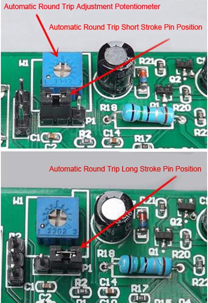
Figure 6.2: Details the automatic round trip adjustment potentiometer and jumper settings for short stroke and long stroke pin positions.
7. Wiring
7.1 External Travel Switch
External travel switches (limit switches) can be connected to the designated pins for precise control of motor movement limits. Refer to Figure 7.1 for connection details.

Figure 7.1: Demonstrates how to connect micro switches to the external travel switch pin for limit control.
7.2 Motor Connections
The board supports both 2-phase 4-wire and 4-phase 5-wire stepper motors. Ensure correct polarity and pin assignment when connecting your motor. Refer to Figure 7.2 for motor wiring pin positions.

Figure 7.2: Illustrates the pin positions for connecting 2-phase 4-wire and 4-phase 5-wire stepper motors, along with positive and negative electrode connections.
8. Troubleshooting
- Motor not running:
- Check power supply voltage (DC 5V-12V).
- Verify motor wiring connections.
- Ensure correct operating mode is selected.
- Running indicator flashes every 2 seconds:
- This indicates overcurrent protection has been triggered (load current exceeds 800mA).
- Lower the working voltage or replace the motor with one that draws less current.
- Motor runs erratically:
- Check for loose connections.
- Ensure speed and round trip adjustments are set correctly for your application.
9. Safety Information
- Always disconnect power before making any wiring changes or adjustments to the board.
- Ensure the power supply voltage is within the specified range (DC 5V-12V) to prevent damage.
- Do not exceed the rated current of 800mA to avoid triggering overcurrent protection or damaging the board.
- Keep the board away from moisture and extreme temperatures.
- This product is intended for DIY and hobbyist use. Exercise caution during operation.
10. Package Contents
- 1x Q-BAIHE Multi Function Micro Stepping Motor Driver Board
- 1x DuPont Line