1. Product Overview
The SmartGen HGM6320T automatic control module is specifically engineered for mobile communication base stations. This controller offers configurable functions to suit various station requirements, enabling automatic control of different generator types. It monitors engine room temperature and battery voltage, and manages mains/load and mains/double Automatic Transfer Switch (ATS) operations. In the event of an alarm, the system can notify servicing personnel via short message.
The HGM6320T features a large Liquid Crystal Display (LCD) with a back-lit screen, offering selectable Chinese and English interfaces. Its design incorporates a compact structure, advanced circuitry, simplified connections, and high reliability, all controlled by a microprocessor and operated via touch buttons.
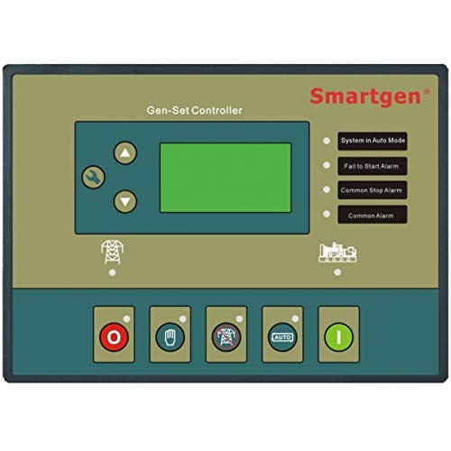
Image 1.1: Front view of the HGM6320T Generator Controller, showing the large LCD screen and touch button interface.
2. Safety Information
- Read all instructions carefully before installation and operation.
- Ensure all power sources are disconnected before performing any wiring or maintenance.
- Installation and servicing should only be performed by qualified personnel.
- Verify all connections are secure and correctly polarized to prevent damage to the unit or connected equipment.
- Protect the controller from moisture, extreme temperatures, and direct sunlight.
3. Setup
3.1 Unpacking
- Carefully remove the HGM6320T controller from its packaging.
- Inspect the unit for any signs of physical damage. If damage is found, contact your supplier immediately.
- Retain the packaging materials for future transport or storage.
3.2 Installation
The HGM6320T controller is designed for panel mounting. Ensure adequate space for ventilation and wiring connections at the rear of the unit.
- Power Supply: Connect the controller to a stable DC power source as specified in the technical data.
- Generator Connections: Wire the generator's start/stop, fuel, and other control signals to the designated terminals.
- Mains/Load Connections: Connect the mains and load sensing inputs, and the ATS control outputs. The controller can manage two ATS units with mains priority.
- Sensor Connections: Connect engine water temperature, oil pressure, and fuel level sensors. An external temperature sensor can be connected to monitor room temperature, enabling automatic air conditioning control.
- Communication Interfaces: Utilize the RS232/RS485 communication interface for remote control, measurement, and communication via the international standard MODBUS protocol.
- SMS Module: If using the SMS function, ensure the SMS module is correctly connected and configured.
4. Operating Instructions
4.1 Control Panel Overview
The front panel features a large LCD for displaying operational parameters and status, along with touch buttons for navigation and control. The LCD provides precise measurement and display of almost all related electricity parameters, water temperature, oil pressure, and fuel level.
4.2 Basic Operation
- Power On: Apply power to the controller. The LCD will illuminate, displaying the initial status or main menu.
- Menu Navigation: Use the touch buttons to navigate through menus and adjust settings. Refer to the on-screen prompts for specific actions.
- Generator Start/Stop: The controller can automatically start and stop the generator based on configured conditions (e.g., mains failure, remote start signal). Manual start/stop options are also available.
4.3 Advanced Features
- SMS Function: Configure up to 5 cell phone numbers to receive SMS messages regarding mains status (normal/abnormal), genset start/stop, power failure, and ATS transfer timer events.
- Crank Disconnect Conditions: The controller supports four configurable conditions for crank disconnect: mains abnormal signal, remote start signal, room temperature, and battery voltage. These conditions can be combined as needed.
- Room Temperature Control: When an external temperature sensor is connected, the controller can monitor room temperature and automatically activate air conditioning if the temperature exceeds a set threshold.
- ATS Control: The HGM6320T can control two ATS units, with mains having priority for power transfer.
- Scheduled Operations: Set a regular time in each month or week for automatic generator startup or shutdown.
- Night Start Prohibition: A function is available to prohibit generator starts during nighttime hours.
- Remote Control & Monitoring: Through the RS232/RS485 interface and MODBUS protocol, remote control, measurement, and communication of the genset can be achieved.
- Room Fan Control: The controller can automatically manage room fans.
- Access Detection: Features access detection to enhance the security of the engine room.
- Time & Energy Tracking: Includes a real calendar, clock, accumulation of running time, and accumulated output electric energy display.
5. Maintenance
- Regular Cleaning: Keep the controller's display and buttons clean using a soft, dry cloth. Avoid abrasive cleaners or solvents.
- Connection Checks: Periodically inspect all wiring connections for tightness and signs of corrosion.
- Firmware Updates: Check the manufacturer's website for any available firmware updates to ensure optimal performance and access to new features.
- Battery Inspection: If the controller has an internal battery for real-time clock or memory backup, ensure it is functioning correctly and replace if necessary according to manufacturer guidelines.
6. Troubleshooting
| Problem | Possible Cause | Solution |
|---|---|---|
| Controller does not power on | No power supply; Incorrect wiring; Blown fuse | Check power input; Verify wiring connections; Replace fuse if necessary |
| Generator fails to start | Low fuel; Low battery voltage; Engine fault; Incorrect start parameters | Check fuel level; Check battery and charging system; Inspect engine for faults; Verify controller start settings |
| Communication error (RS232/RS485) | Incorrect wiring; Wrong communication settings; Damaged cable | Check communication wiring; Verify baud rate and protocol settings; Replace cable if damaged |
| SMS messages not sent | SMS module not connected; Incorrect phone numbers; Network issues | Ensure SMS module is connected and powered; Verify configured phone numbers; Check cellular network signal |
7. Specifications
| Feature | Detail |
|---|---|
| Brand | SmartGen |
| Model | HGM6320T |
| Item Weight | 0.9 Kilograms |
| Manufacturer | SMARTGEN |
| Display | Large LCD with back-light |
| Interface Language | Chinese, English (selectable) |
| Control Type | Microprocessor, Touch Button |
| Communication | RS232/RS485, MODBUS protocol |
| ATS Control | 2 ATS units, mains priority |
| Special Features | SMS function, Room temperature monitoring, Scheduled start/stop, Night start prohibition, Room fan control, Access detection, Real calendar/clock, Running time/energy accumulation |
8. Warranty and Support
SmartGen products are typically covered by a manufacturer's warranty against defects in materials and workmanship. The specific duration and terms of the warranty may vary by region and purchase date. Please refer to the warranty card included with your product or contact your local SmartGen distributor for detailed information.
For technical support, troubleshooting assistance, or inquiries regarding spare parts, please contact SmartGen-America or your authorized SmartGen dealer. When contacting support, please have your product model (HGM6320T) and serial number available.
Online Resources: Visit the official SmartGen website for product documentation, FAQs, and software updates.