1. Introduction
The Q-BAIHE GM328 is a versatile multi-functional transistor tester designed for automatic detection and analysis of various electronic components. It can identify NPN and PNP transistors, FETs, diodes, dual diodes, thyristors, and SCRs, automatically determining their pinout. Additionally, this device functions as a square wave and PWM signal generator, making it a valuable tool for electronics enthusiasts and professionals.
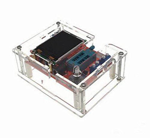
Image 1.1: The Q-BAIHE GM328 Transistor Tester, fully assembled in its protective clear acrylic case.
2. Safety Information
Important Safety Precaution: Before measuring capacitance, ensure the capacitor is fully discharged. Failure to do so may cause severe damage to the GM328 tester.
Always handle electronic components and the tester with care. Avoid exposing the device to moisture, extreme temperatures, or strong electromagnetic fields. Use only the specified power supply voltage range.
3. Package Contents
Verify that all components are present in your package:
- GM328 Transistor Tester PCB (with firmware welded)
- Acrylic Case Components (unassembled)
- Mounting Hardware (screws, standoffs)
- Additional small electronic components (if purchased as a kit for case assembly)

Image 3.1: Overview of the GM328 Transistor Tester components, including the main PCB, acrylic case parts, and hardware.
4. Assembly Instructions
The main circuit board of the GM328 comes with firmware pre-welded. The acrylic case, however, requires assembly to protect the circuit board.
- Carefully unpack all acrylic case components and mounting hardware.
- Identify the base plate and top plate of the case.
- Attach the side panels to the base plate using the provided screws and nuts. Ensure all cutouts align correctly.
- Gently place the GM328 PCB into the assembled lower part of the case, aligning the display and test sockets with their respective openings.
- Secure the PCB using the standoffs and screws, ensuring it is stable and does not short circuit against the case.
- Finally, attach the top plate of the acrylic case, securing it with the remaining screws.
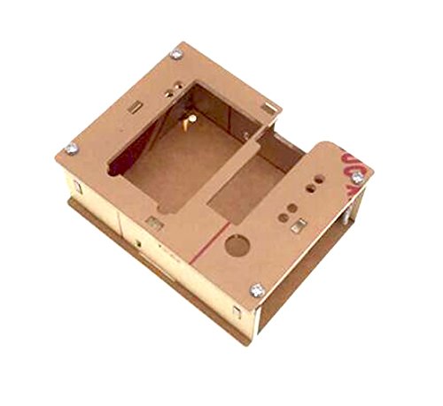
Image 4.1: Disassembled acrylic case parts before assembly.

Image 4.2: The main PCB board being fitted into the lower section of the acrylic case.
5. Powering the Device
The GM328 Transistor Tester can be powered by either a 9V battery or an external DC power supply.
- 9V Battery: Connect a standard 9V battery (not included) to the battery clip connector on the PCB.
- DC Power Supply: Alternatively, connect a DC power supply with a voltage range of 6.8V to 12V to the DC input jack. Ensure correct polarity.
The device consumes approximately 30mA during operation.
6. Basic Operation (Component Testing)
The GM328 features a ZIF (Zero Insertion Force) socket for easy component testing. The device automatically identifies the component type and pinout.
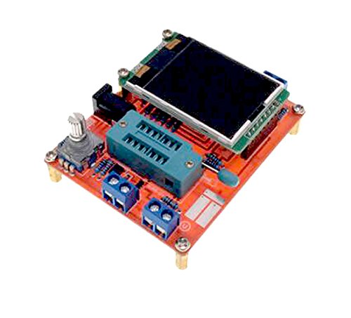
Image 6.1: The GM328 PCB, highlighting the ZIF socket for component insertion and test points.
- Power On: Connect the power supply. The LCD screen will illuminate.
- Insert Component: Open the lever of the ZIF socket. Insert the leads of the component (e.g., transistor, diode, resistor, capacitor) into the desired test points (typically 1, 2, and 3). Close the lever to secure the component.
- Start Test: Press the test button (usually a rotary encoder with a push function). The tester will automatically analyze the component.
- Read Results: The LCD will display the component type, pinout (e.g., EBC for a transistor), and measured parameters (e.g., capacitance, resistance, forward voltage drop).
- Remove Component: Open the ZIF socket lever and carefully remove the component.
For two-lead components like resistors and capacitors, you can use any two of the three test points. For diodes, ensure correct polarity if you want to measure forward voltage drop accurately, though the tester will identify it regardless.
7. Advanced Functions (Signal Generation)
The GM328 can also function as a signal generator for square waves and Pulse Width Modulation (PWM) signals.
- Accessing Signal Generator: Navigate through the menu options using the rotary encoder. Look for a menu item related to 'Signal Generator' or 'PWM'.
- Square Wave Generation: Select the square wave option. You can typically adjust the frequency of the square wave output. The signal will be available on designated output pins (refer to the PCB markings or on-screen instructions).
- PWM Signal Generation: Select the PWM option. You can usually set both the frequency and the duty cycle of the PWM signal. This is useful for controlling motors or testing digital inputs.
Consult the on-screen menu for specific instructions on adjusting parameters and identifying output pins for signal generation.
8. Specifications
| Feature | Specification |
|---|---|
| Type | Firmware (welded) |
| Display | 160*128 LCD |
| Power Supply | 1 * 9V Battery (not included); DC 6.8-12V |
| Current Consumption | Approx. 30mA |
| Resistance Measurement Range | Max. 50MΩ |
| Resistance Resolution | 0.01Ω |
| Capacitance Measurement Range | 25pF~100mF |
| Capacitance Resolution | 1pF |
| DC Voltage Measurement | Up to 50V |
| Min. Operating Voltage | 6.8 Volts (DC) |
| Screen Size | 3.7 * 3cm / 1.45 * 1.18in |
| PCB Size | 7.8 * 6.2cm / 3.1 * 2.44in |
| Product Weight | 75g |
| Measurement Type | LCR Meter, Voltmeter |
9. Maintenance and Care
- Cleaning: Use a soft, dry cloth to clean the device. Do not use abrasive cleaners or solvents.
- Storage: Store the tester in a dry, dust-free environment away from direct sunlight and extreme temperatures.
- Battery Replacement: If using a 9V battery, replace it when the display indicates low power or when the device fails to power on.
- Component Insertion: Always use the ZIF socket carefully to avoid bending or damaging component leads or the socket itself.
10. Troubleshooting
- Device does not power on: Check the battery connection or external DC power supply. Ensure the battery has sufficient charge or the power adapter is functioning correctly and within the specified voltage range.
- Incorrect readings: Ensure the component is properly inserted into the ZIF socket. Verify that the component is not damaged. For capacitors, ensure they are fully discharged before testing.
- Display issues: If the display is dim or flickering, check the power supply. If the display shows garbled text, try restarting the device.
- Component not identified: Some specialized or very low-value components might not be accurately identified. Ensure the component is within the tester's measurement range.
11. Warranty and Support
For warranty information and technical support, please refer to the seller or manufacturer's official channels. Keep your purchase receipt as proof of purchase.