Apem B07FPFTT2B
Apem Coded Rotary Switches SMT, Shaped 16 Position User Manual
1. Introduction
This manual provides comprehensive instructions for the Apem Coded Rotary Switches, SMT, Shaped 16 Position. This compact electronic component is designed for surface mount applications, offering 16 distinct positions for setting parameters or selecting operational modes in various electronic circuits. Its coded output simplifies integration into digital systems.
2. Safety Information
Please observe the following safety guidelines to ensure proper handling and installation of the rotary switch:
- Professional Installation: Installation should be performed by qualified personnel familiar with electronic components and surface mount technology.
- Electrostatic Discharge (ESD) Precautions: Handle the switch in an ESD-safe environment to prevent damage to sensitive internal components.
- Power Disconnection: Ensure all power is disconnected from the circuit board before installation or removal of the switch.
- Proper Soldering: Use appropriate soldering techniques and equipment for SMT components to avoid overheating or damaging the switch.
- Physical Damage: Avoid applying excessive force or impact to the switch, as this can compromise its functionality and integrity.
3. Setup and Installation
The Apem Coded Rotary Switch is designed for surface mount installation on printed circuit boards (PCBs).
3.1 Unpacking
Carefully remove the switch from its packaging. Inspect the component for any visible damage before proceeding with installation.
3.2 Mounting and Soldering
- PCB Preparation: Ensure the PCB pads are clean and properly prepared for SMT soldering.
- Component Placement: Position the rotary switch accurately on the designated pads on the PCB. Pay attention to the orientation markings, if any, to ensure correct pin alignment.
- Soldering: Solder the switch to the PCB using standard SMT reflow or hand soldering techniques. Ensure proper solder joint formation on all pins. Avoid excessive heat or prolonged soldering times.
3.3 Electrical Connection
The switch provides a coded output. Refer to the specific datasheet for the exact pinout and coding scheme (e.g., BCD, hexadecimal). Connect the output pins to the corresponding input pins of your microcontroller or logic circuit. Ensure proper grounding and power supply connections as per your circuit design.
4. Operating the Switch
The Apem Coded Rotary Switch allows for selection of one of 16 distinct positions.
4.1 Position Selection
To change the selected position, use a small screwdriver or appropriate tool to rotate the central shaft of the switch. The switch provides tactile feedback (clicks) for each position, ensuring precise selection. The top surface of the switch is marked with numbers (0-9) and potentially letters (A-F) or other indicators to denote the current position.
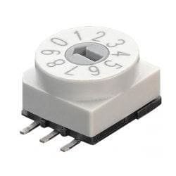
Figure 1: Apem 16-position coded rotary switch. The image shows the top view of the white switch with a gray central shaft, indicating positions 0 through 9 and beyond, typically adjusted with a screwdriver.
4.2 Coded Output
Each of the 16 positions corresponds to a unique binary or BCD (Binary Coded Decimal) output code on the switch's pins. Your circuit should be designed to interpret this code to perform the desired function (e.g., setting a frequency, selecting an operating mode, or configuring a device address).
5. Maintenance
The Apem Coded Rotary Switch is a sealed component designed for long-term reliability with minimal maintenance.
- Cleaning: If necessary, gently clean the exterior of the switch with a soft, dry cloth. Avoid using harsh chemicals or solvents.
- Inspection: Periodically inspect the switch for any signs of physical damage or loose connections, especially in environments subject to vibration or extreme temperatures.
- No Internal Servicing: Do not attempt to open or service the internal components of the switch, as this will void any potential warranty and may damage the device.
6. Troubleshooting
If you encounter issues with the rotary switch, consider the following troubleshooting steps:
- No Output/Incorrect Output:
- Verify all solder joints are secure and free from shorts or cold joints.
- Check the electrical connections to the PCB and ensure they match the datasheet's pinout.
- Confirm that your circuit's logic is correctly interpreting the coded output from the switch for each position.
- Ensure the switch is properly grounded and receiving appropriate power, if applicable.
- Difficulty Rotating:
- Ensure you are using the correct tool (e.g., a small flat-head screwdriver) for adjustment.
- Check for any physical obstructions or debris around the rotating mechanism.
- Do not force the switch; excessive force can cause internal damage.
- Intermittent Operation:
- Inspect for hairline cracks in solder joints or the PCB itself.
- Ensure the switch is securely mounted and not subject to excessive vibration.
If problems persist after following these steps, consult the product datasheet or contact Apem technical support.
7. Specifications
| Brand | Apem |
| Model Number (ASIN) | B07FPFTT2B |
| Product Type | Coded Rotary Switch |
| Mounting Type | SMT (Surface Mount Technology) |
| Number of Positions | 16 |
| Output Type | Coded (e.g., BCD, Hexadecimal - refer to datasheet for specific coding) |
| Adjustment Method | Screwdriver Adjustable |
Ask a question about this manual
Ask about setup, troubleshooting, compatibility, parts, safety, or missing instructions. Manuals+ will review the question and use this page’s manual context to help answer it.