1. Introduction
This manual provides detailed instructions for the NOYITO AC to DC Precision Buck Power Supply Module (Model: NOADPB53). This isolated step-down DC module is designed to convert AC input voltage (100-264V) to a stable 5V DC output with a maximum current of 3A (3000mA). It features wide voltage range input, overload, short circuit, and over-temperature protection, all within an ultra-small form factor and high efficiency.
2. Safety Information
Please read and understand all safety instructions before installing or operating this module. Failure to follow these instructions may result in electric shock, fire, or damage to the product or connected devices.
- Electrical Hazard: This module operates with high AC voltage. Ensure power is disconnected before making any connections or performing maintenance.
- Qualified Personnel: Installation and wiring should only be performed by qualified personnel familiar with electrical safety standards.
- Insulation: Ensure proper insulation for all connections to prevent short circuits and electrical hazards.
- Ventilation: Provide adequate ventilation around the module to prevent overheating, especially during high load operation.
- Environment: Do not expose the module to moisture, extreme temperatures, or corrosive environments.
- Overload Protection: While the module has built-in overload protection, avoid exceeding the rated output current (3A) to ensure stable operation and longevity.
3. Product Overview
The NOYITO AC to DC Precision Buck Power Supply Module is a compact and efficient solution for various electronic projects requiring a stable 5V DC power source from an AC input.
3.1 Module Components
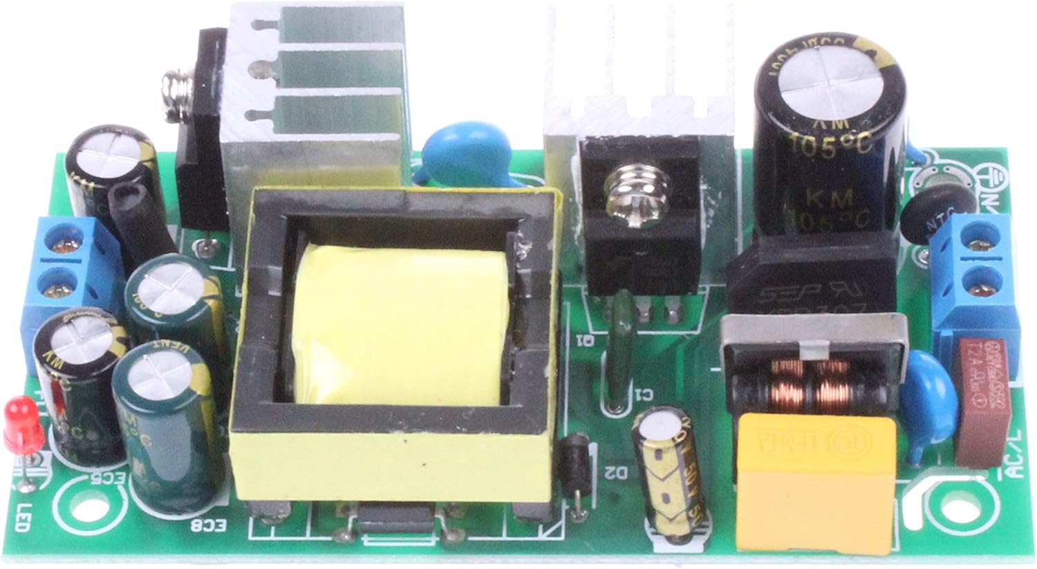
Figure 1: Top View of the Power Supply Module. This image shows the top-down perspective of the module, highlighting the main transformer, capacitors, heat sinks, and input/output terminals. The green PCB is visible with various electronic components mounted.

Figure 2: Angled View of the Power Supply Module. This perspective provides a clearer view of the module's three-dimensional structure, including the height of components like the transformer and heat sinks, and the terminal blocks for connections.

Figure 3: Side View of the Power Supply Module. This view illustrates the compact profile of the module, showing the arrangement of components from the side, including the input and output terminal blocks.

Figure 4: Bottom View of the Power Supply Module. This image displays the underside of the printed circuit board (PCB), showing the solder points and traces. Mounting holes are visible at the corners.
3.2 Dimensional Drawing

Figure 5: Dimensional Drawing. This technical drawing provides precise measurements of the module in millimeters, including mounting hole positions and overall dimensions, crucial for integration into enclosures or projects. Key labels like ACL, ACN for AC input and V+, GND for DC output are indicated.
4. Specifications
| Parameter | Value |
|---|---|
| Input Voltage Range | AC 100-264V (120V nominal) |
| Input Current | < 0.2A (Average 0.03A-0.1A) |
| Frequency Range | 47-63Hz |
| Efficiency | ~80% |
| Start Surge Current | COLD START 30A/230V AC |
| Leakage Current | < 2mA / 220V AC |
| Output Voltage | 5V ±1% |
| Output Current | 3A (3000mA) |
| Rated Power | 15W |
| Ripple | < 60mVp-p |
| Output Accuracy | ±1% |
| Voltage Regulation Rate | ±1% |
| Load Adjustment Rate | ±1.2% |
| Output Adjustable Range | Not adjustable |
| Establish, Rise, Hold Time | 500ms, 80ms, 80ms / 220V AC |
| Over Power Protection | 150-170% rated power (Auto-recovery) |
| Overvoltage Protection | VH: >50% |
| DC Short Circuit Protection | Intermittent separation (Auto-recovery) |
| Working Temperature | -15°C to +50°C @ 100% LOAD, +60°C @ 60% LOAD |
| Working Humidity | 20%-90% RH |
| Storage Temperature, Humidity | -20°C to +85°C, 10%-95% RH |
| Withstand Voltage (I/P-O/P) | 1KV AC 1min |
| Insulation Resistance (I/P-O/P) | 500VDC / 100M Ohms |
| Product Dimensions | 3.43 x 1.81 x 0.98 inches (87.1 x 46 x 24.9 mm) |
| Item Weight | 0.81 ounces (23 grams) |
| Model Number | NOADPB53 |
5. Setup
Careful setup is essential for safe and reliable operation of the power supply module.
5.1 Wiring Diagram
Refer to Figure 5 (Dimensional Drawing) for the pinout and connection points. The module features screw terminals for both AC input and DC output.
- AC Input: Connect your AC power source (100-264V) to the terminals labeled ACL and ACN. Ensure correct polarity if applicable, though AC is typically non-polarized.
- DC Output: Connect your load to the terminals labeled V+ (positive 5V DC) and GND (ground).
5.2 Installation Steps
- Power Off: Ensure all power sources are disconnected before beginning installation.
- Mounting: Secure the module in a suitable enclosure or mounting surface using the provided mounting holes. Ensure adequate clearance for ventilation.
- AC Input Wiring: Connect the AC input wires to the ACL and ACN screw terminals. Tighten the screws firmly to ensure good electrical contact.
- DC Output Wiring: Connect the DC output wires from the V+ and GND screw terminals to your target device or circuit. Observe correct polarity. Tighten the screws firmly.
- Inspect Connections: Double-check all wiring for correctness, secure connections, and proper insulation to prevent short circuits.
- Power On: Once all connections are verified, apply AC power to the module. The module should begin operating and provide 5V DC output.
6. Operating Instructions
The NOYITO AC to DC Precision Buck Power Supply Module is designed for continuous operation within its specified parameters.
- Input Voltage: The module accepts a wide AC input voltage range from 100V to 264V.
- Output Voltage: It provides a stable 5V DC output. This output is not adjustable.
- Output Current: The maximum continuous output current is 3A. Do not exceed this limit to prevent damage to the module or connected devices.
- Protection Features: The module includes built-in protection against over-power, over-voltage, and DC short circuits. In case of a fault, the protection mechanism will activate and automatically restore operation once the fault is removed.
- Temperature: Ensure the module operates within the specified working temperature range (-15°C to +50°C at 100% load). Adequate airflow is crucial for heat dissipation.
7. Maintenance
The NOYITO Power Supply Module requires minimal maintenance. Regular checks can help ensure its longevity and reliable performance.
- Cleaning: Periodically inspect the module for dust accumulation. If necessary, gently clean the module with a soft, dry brush or compressed air. Ensure power is disconnected before cleaning.
- Connection Checks: Occasionally check all wiring connections to ensure they remain tight and secure. Loose connections can lead to intermittent operation or overheating.
- Environmental Conditions: Verify that the operating environment remains within the specified temperature and humidity ranges.
- Visual Inspection: Look for any signs of physical damage, discoloration, or bulging capacitors, which may indicate a fault.
8. Troubleshooting
If you encounter issues with your power supply module, refer to the table below for common problems and their solutions.
| Problem | Possible Cause | Solution |
|---|---|---|
| No output voltage | No AC input power Loose wiring connections Module fault Overload/Short circuit protection activated | Verify AC input power is present. Check and tighten all input and output wiring. Disconnect load and re-test. If still no output, module may be faulty. Reduce load or remove short circuit. Module should auto-recover. |
| Output voltage is unstable or incorrect | Excessive load Poor input power quality Module fault | Ensure load current does not exceed 3A. Verify stable AC input voltage within 100-264V range. If problem persists, module may be faulty. |
| Module is overheating | Insufficient ventilation Excessive ambient temperature Overload | Ensure adequate airflow around the module. Operate within specified temperature range. Reduce load current to below 3A. |
| Module repeatedly shuts down | Persistent overload or short circuit Over-temperature protection repeatedly activating | Identify and resolve the cause of the overload or short circuit. Improve ventilation and reduce load. |
9. Warranty and Support
Specific warranty information for this product was not provided in the available product data. For any technical support, inquiries, or to report issues, please contact NOYITO customer service through your purchase platform or the official NOYITO website.
A dimensional drawing download link was provided in the product information: Product Dimensional Drawing.