
1. Introduction
This manual provides detailed instructions for the proper use and maintenance of the Ximimark ST-Link V2 Shell Programming Unit, Model NE826. This device functions as a mini emulator and downloader for STM8 and STM32 series microcontrollers, facilitating program debugging and flashing. Please read this manual thoroughly before operating the device to ensure correct usage and to prevent damage.
2. Safety Information
Observe the following safety precautions to prevent damage to the device or connected components:
- Ensure proper voltage levels when connecting to target boards. The unit provides 3.3V and 5.0V outputs.
- Avoid short circuits on the output I/O ports. The unit includes protection, but excessive current can still cause damage.
- Do not expose the device to moisture, extreme temperatures, or static electricity.
- Handle the unit with care to avoid physical damage.
- Only use the provided DuPont lines or compatible connectors for wiring.
3. Package Contents
Verify that all items are present in the package:
- 1 x Ximimark ST-Link V2 Shell Programming Unit (Model NE826)
- 1 x 20CM DuPont Line (for connections)
4. Product Overview
The ST-Link V2 is a compact programming unit designed for debugging and programming STM8 and STM32 microcontrollers. It features a USB interface for connection to a host computer and a 10-pin connector for interfacing with the target microcontroller.

Figure 4.1: Ximimark ST-Link V2 Shell Programming Unit with included DuPont lines. The blue unit has a USB connector on one end and a 10-pin header on the other, with colored wires connected.
4.1 Pinout Diagram
The 10-pin interface provides various signals for programming and debugging. The pin definitions are clearly marked on the unit's shell.

Figure 4.2: Close-up view of the ST-Link V2 unit showing the pinout labels. Pins include RST, SWIM, GND, 3.3V, 5.0V, SWCLK, SWDIO, and additional GND, 3.3V, 5.0V pins.
The pin assignments are as follows:
| Pin No. | Label | Description |
|---|---|---|
| 1 | RST | Reset pin for the target microcontroller. |
| 2 | SWCLK | Serial Wire Clock (SWD interface). |
| 3 | SWIM | Single Wire Interface Module (for STM8). |
| 4 | SWDIO | Serial Wire Data Input/Output (SWD interface). |
| 5 | GND | Ground connection. |
| 6 | GND | Ground connection. |
| 7 | 3.3V | 3.3 Volt power output. |
| 8 | 3.3V | 3.3 Volt power output. |
| 9 | 5.0V | 5.0 Volt power output. |
| 10 | 5.0V | 5.0 Volt power output. |
5. Setup
Follow these steps to set up your ST-Link V2 programming unit:
- Driver Installation: Before connecting the ST-Link V2 to your computer, ensure that the necessary drivers are installed. These drivers are typically part of the STMicroelectronics development environment (e.g., STM32CubeIDE, Keil MDK, IAR Embedded Workbench) or can be downloaded from the STMicroelectronics website.
- Connect to Computer: Plug the USB connector of the ST-Link V2 unit into an available USB port on your computer. The operating system should recognize the device.
- Connect to Target Microcontroller: Use the provided 20CM DuPont lines to connect the ST-Link V2 to your target STM8 or STM32 microcontroller board. Refer to the pinout diagram (Figure 4.2) and your target board's documentation for correct connections.
- For STM32 (SWD interface): Connect SWCLK, SWDIO, GND, and optionally 3.3V or 5.0V if powering the target from the ST-Link V2.
- For STM8 (SWIM interface): Connect SWIM, GND, and optionally 3.3V or 5.0V.
- Ensure the RST pin is connected if your programming software requires it for reset operations.
- Power Output: The ST-Link V2 can provide 3.3V and 5.0V power to the target board. Use these outputs cautiously and only if your target board requires external power from the programmer and can handle the specified voltage.
Video 5.1: An overview of the ST-Link V2 Mini Metal Shell STM8 STM32 Emulator Downloader, demonstrating its physical appearance and components. This video is provided by the seller and shows the device in operation.
6. Operating Instructions
Once the ST-Link V2 is connected to your computer and target microcontroller, you can proceed with programming or debugging:
- Launch Development Environment: Open your preferred IDE or programming software (e.g., STM32CubeIDE, Keil uVision, IAR Embedded Workbench, STM8CubeProgrammer).
- Select ST-Link Debugger: In your software's project settings or debug configuration, select "ST-Link" as the debugger/programmer interface.
- Connect to Target: Initiate a connection to the target microcontroller. The software should detect the ST-Link V2 and the connected chip.
- Program/Flash Firmware: Load your compiled firmware (.hex, .elf, or .bin file) into the software and use the "Program" or "Download" function to flash it onto the target microcontroller.
- Debug: If debugging, set breakpoints, step through code, and monitor variables as needed.
- Automatic Firmware Upgrade: The ST-Link V2 supports automatic firmware upgrades. The unit is factory-upgraded to the latest firmware (V2.J17.S4). If a newer firmware version is available, your development environment may prompt you to update it. Follow the on-screen instructions to complete the upgrade.
7. Maintenance
The ST-Link V2 is a low-maintenance device. Follow these guidelines to ensure its longevity:
- Keep the unit clean and free from dust and debris. Use a soft, dry cloth for cleaning.
- Store the unit in a dry environment, away from direct sunlight and extreme temperatures.
- Inspect the DuPont lines and connectors periodically for any signs of wear or damage. Replace them if necessary.
- Ensure the USB connector is clean and free of obstructions.
8. Troubleshooting
If you encounter issues with your ST-Link V2, refer to the following common problems and solutions:
| Problem | Possible Cause | Solution |
|---|---|---|
| ST-Link V2 not recognized by computer. | Missing or incorrect drivers. Faulty USB cable/port. | Install/reinstall ST-Link drivers. Try a different USB port or cable. Check Device Manager for driver status. |
| Cannot connect to target microcontroller. | Incorrect wiring. Target board not powered. Incorrect target selection in software. Firmware protection. | Verify all connections according to the pinout. Ensure target board is powered. Select the correct microcontroller type in your IDE. Check if the target microcontroller has read/write protection enabled. |
| Programming/Flashing fails. | Corrupted firmware file. Insufficient power to target. Incorrect memory address. | Ensure your firmware file is valid. Confirm target board is adequately powered. Verify memory addresses in programming software. |
| Device firmware update fails. | Interrupted connection. Software issue. | Ensure a stable USB connection. Restart the programming software and try again. Refer to STMicroelectronics documentation for specific update procedures. |
9. Specifications
- Model: NE826
- Supported Microcontrollers: STM8 series, STM32 series
- Interface: USB 2.0 (Host), 10-pin header (Target)
- Output Voltage: 3.3V, 5.0V (selectable via wiring)
- Firmware: Automatically upgradable (factory default V2.J17.S4)
- Dimensions: Approximately 55mm x 20mm x 12mm (L x W x H)
- Item Weight: 0.176 ounces (approx. 5 grams)
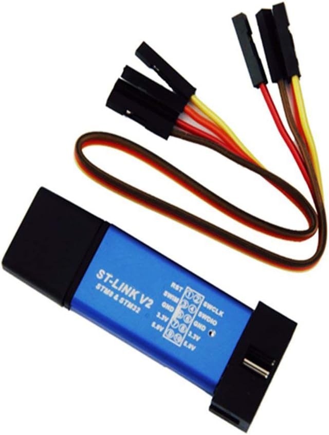
Figure 9.1: Diagram showing the approximate dimensions of the ST-Link V2 unit: 55mm (2.16 inches) length, 20mm (0.78 inches) width, and 12mm (0.47 inches) height. The included line length is 18cm (7.08 inches).
10. Warranty and Support
For warranty information and technical support, please contact your retailer or the manufacturer, Ximimark. Keep your purchase receipt as proof of purchase.
- Manufacturer: Ximimark
- Contact: Refer to the seller's contact information on the platform where the product was purchased.
- Online Resources: For detailed technical documentation and software downloads, visit the official STMicroelectronics website.