DollaTek MX1508 Dual Channel DC Motor Driver Module
DollaTek Dual Channel DC Motor Driver Module (MX1508)
Instruction Manual
1. Introduction
This manual provides detailed instructions for the DollaTek Dual Channel DC Motor Driver Module, which utilizes the MX1508 chip. This module is designed to drive two DC motors or a single 4-wire two-phase stepper motor. It is ideal for various applications including smart cars, toy cars, and robotics due to its compact size, low power consumption, and integrated thermal protection.
Note: While often associated with L298N modules, this product uses the MX1508 chip, which has different voltage characteristics. Please refer to the specifications carefully.
2. Safety Information
WARNING:
- Ensure correct power polarity. Reversing positive and negative power connections will cause damage to the circuit.
- Avoid short-circuiting the output to ground or between outputs. While the chip has thermal protection, sustained short circuits or motor stalls at voltages near or exceeding 10V and peak currents above 2.5A can still lead to chip damage.
- Use a compliant power supply.
- Avoid extreme heat and ensure proper ventilation for optimal performance and longevity.

Image: A warning label indicating general safety precautions for electronic devices.
3. Product Overview
The DollaTek Dual Channel DC Motor Driver Module is a compact and efficient solution for motor control. It features a dual H-bridge design, allowing independent control of two DC motors or a single stepper motor. The module incorporates a low on-resistance MOS switch, minimizing heat generation and eliminating the need for an external heatsink.

Image: A single DollaTek motor driver module, highlighting its compact design and components.
Key Features:
- Dual H-bridge motor driver, capable of driving two DC motors or one 4-wire two-phase stepper motor.
- Built-in thermal protection circuit (TSD) with hysteresis effects, preventing damage from motor stalls.
- Ultra-small size, suitable for integration into various projects.
- Low standby current (less than 0.1uA) for energy efficiency.
- Built-in common conduction circuit ensures motors do not malfunction if input pins are left floating.
4. Technical Specifications
| Parameter | Value |
|---|---|
| Module Supply Voltage | 2V - 10V DC |
| Signal Input Voltage | 1.8V - 7V |
| Single Operating Current | 1.5A (Peak 2.5A) |
| Low Standby Current | < 0.1uA |
| Product Dimensions (L x W x H) | 24.7 x 21 x 5 mm |
| Mounting Hole Diameter | 2 mm |
| Weight | 5g (per module) |
| Operating Temperature | Up to 85°C |
| ASIN | B07F9LH4PJ |
| UPC | 742548986186 |

Image: The motor driver module displaying its physical dimensions and weight.
5. Setup and Connections
Pinout Diagram:
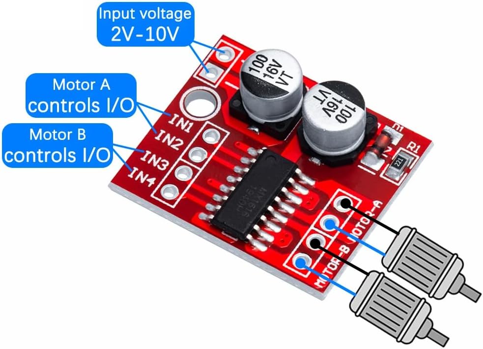
Image: Pinout diagram of the motor driver module, illustrating input voltage and control pins for Motor A and Motor B.
Connection Guide:

Image: A detailed wiring diagram showing how to connect the power supply, control signals, and motors to the module.
- Power Supply: Connect your DC power source (2V-10V) to the '+' and '-' terminals on the module. Ensure correct polarity.
- Motor Connections: Connect Motor A to the 'MOTOR-A' terminals and Motor B to the 'MOTOR-B' terminals. The module can drive two independent DC motors.
- Control Signal Input: The module has four input pins: IN1, IN2, IN3, and IN4. These pins receive control signals from your microcontroller (e.g., Arduino, Raspberry Pi). The signal input voltage range is 1.8V-7V.
- IN1 and IN2 control Motor A.
- IN3 and IN4 control Motor B.
6. Operating Instructions
Motor Control Modes:
The motor's direction and speed are controlled by applying high (1), low (0), or Pulse Width Modulation (PWM) signals to the input pins. PWM adjusts the duty cycle to change the motor's speed.
| DC Motor | Mode | IN1 | IN2 | IN3 | IN4 |
|---|---|---|---|---|---|
| MOTOR-A | Forward | 1/PWM | 0 | ||
| Reverse | 0 | 1/PWM | |||
| Standby | 0 | 0 | |||
| Brake | 1 | 1 | |||
| MOTOR-B | Forward | 1/PWM | 0 | ||
| Reverse | 0 | 1/PWM | |||
| Standby | 0 | 0 | |||
| Brake | 1 | 1 |
Image: Table detailing the control logic for DC motors, including Forward, Reverse, Standby, and Brake modes using IN1-IN4 pins.
- '1' represents a high logic level.
- '0' represents a low logic level.
- 'PWM' indicates a Pulse Width Modulated wave, used to adjust the motor's speed by varying the duty cycle.
- IN1 and IN2 control MOTOR-A; IN3 and IN4 control MOTOR-B. These two motor channels are completely independent.
- The INx anti-input common conduction function means that if an input pin is left floating, it is equivalent to a low input.
7. Maintenance
- Keep the module clean and free from dust and moisture.
- Regularly inspect connections for any loose wires or signs of corrosion.
- Ensure adequate airflow around the module, especially during continuous operation, to prevent overheating.
- Avoid physical stress or impact to the module.
8. Troubleshooting
- Motor not moving: Check power supply voltage and polarity. Verify control signals (IN1-IN4) are correctly applied according to the operating table. Ensure motors are properly connected.
- Motor moving erratically: Check for stable power supply. Ensure control signals are clean and not fluctuating. Verify motor connections are secure.
- Module overheating: Reduce motor load or ensure the supply voltage is within the specified 2V-10V range. Check for short circuits in motor wiring. The built-in thermal protection will temporarily shut down the chip if it overheats, and it will recover once the temperature drops.
- Chip burned out: This typically occurs due to reversed power polarity, sustained short circuits, or exceeding the maximum voltage/current limits. Always double-check wiring before applying power.
9. Warranty and Support
DollaTek products are manufactured with quality in mind. For specific warranty details, please refer to the documentation provided with your purchase or contact the seller directly.
Contact Information:
Manufacturer: HONGKONG YINGLI INTERNATIONAL TRADING CO LIMITED
Address: RM502C, 5/F, HO KING COMM CTR, 2-16 FAYUEN ST, MONGKOK KOWLOON, 999077 HONGKONG
Tel: +8615361577769
Email: info@dollatek.com
EU Representative: Dahuang OÜ
Address: Harju maakond, Tallinn, Kesklinna linnaosa, Veskiposti tn 2-1002, 10138, Estonia
Tel: +3726407506
Email: info@oudahuang.com

Image: Product packaging displaying manufacturer and EU representative contact details.

Image: Compliance markings (EC REP, RoHS, CE) and additional manufacturer details.
Related Documents - MX1508 Dual Channel DC Motor Driver Module
 |
Digital Technology Equipment List - RoboCoast A comprehensive equipment list from RoboCoast, detailing various electronic components, sensors, motors, chassis, and power supply units suitable for robotics and digital technology projects. Includes product names, specifications, and purchase links. |
Ask a question about this manual
Ask about setup, troubleshooting, compatibility, parts, safety, or missing instructions. Manuals+ will review the question and use this page’s manual context to help answer it.