1. Introduction
This manual provides comprehensive instructions for the safe and effective operation of the GW Instek GPM-8213 Digital Power Meter. The GPM-8213 is a high-precision instrument designed for measuring various power parameters in electrical systems. It features a 4-inch TFT LCD, a five-digit measurement display, and the capability to measure 19 different power parameters. This device is suitable for applications in research and development, design verification, and quality control.
Please read this manual thoroughly before operating the device to ensure proper usage and to prevent damage to the instrument or injury to personnel.
2. Safety Information
Observe the following safety precautions to prevent electric shock, injury, or damage to the instrument:
- Always connect the instrument to a properly grounded power outlet.
- Do not operate the instrument in wet or damp conditions.
- Ensure all connections are secure before applying power.
- Do not exceed the maximum input ratings specified for voltage and current.
- Refer to the rear panel warnings regarding input removal before opening the casing.
- Only qualified personnel should perform maintenance or repairs.
3. Product Overview
3.1 Front Panel

Figure 3.1: Front view of the GPM-8213 Digital Power Meter, showing the 4-inch TFT LCD display with measurement parameters like Vrms, Irms, Vcf, and Icf. The control buttons for mode, setup, hold, and integrator functions are visible, along with the current and voltage input terminals.

Figure 3.2: Front view of the GPM-8213 Digital Power Meter, displaying additional parameters such as V_Auto, I_Auto, Vcf, Icf, Ipp, and Vpp, illustrating the detailed measurement capabilities of the device. Buttons for 'Enlarge', 'Integral', and 'Parameter' are also visible on the screen.
The front panel features a 4-inch TFT LCD for displaying measurement results and settings. Navigation buttons allow users to select measurement modes, configure settings, and control integral functions. Dedicated input terminals for current (I+, I-) and voltage (V+, V-) are clearly labeled with maximum ratings.
3.2 Rear Panel
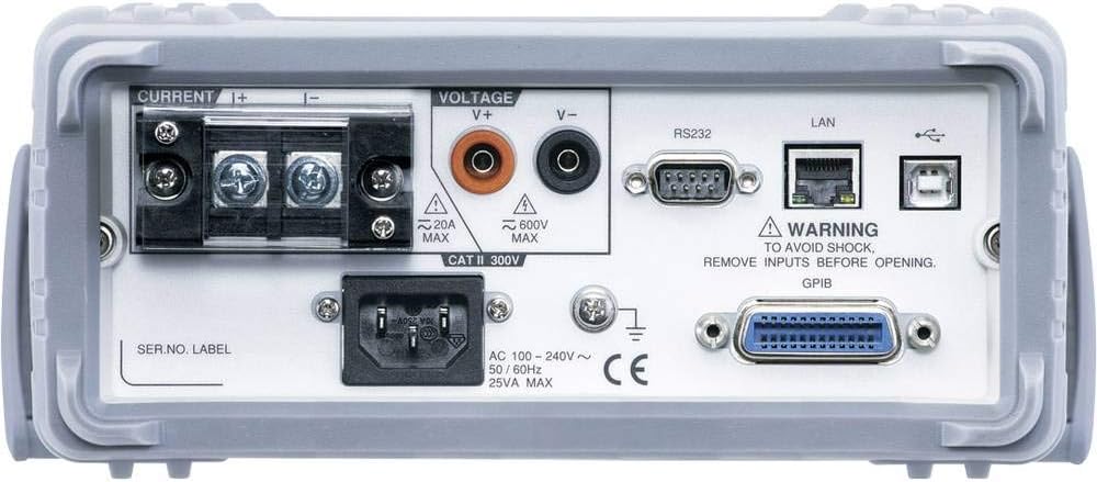
Figure 3.3: Rear view of the GPM-8213 Digital Power Meter, showing the current and voltage input terminals, the AC power inlet, and various communication interfaces including RS232, LAN, USB, and an optional GPIB port.
The rear panel provides additional input terminals for current and voltage, the AC power input, and various communication interfaces including RS-232C, LAN, and USB. An optional GPIB interface may also be present.
4. Setup
4.1 Power Connection
- Ensure the power switch on the front panel is in the OFF position.
- Connect the supplied AC power cord to the power inlet on the rear panel.
- Plug the other end of the power cord into a grounded AC power outlet (100-240V AC, 50/60Hz).
4.2 Input Terminal Connections
Connect the device under test (DUT) to the appropriate input terminals. The GPM-8213 offers both front and rear panel input terminals.
- Voltage Input: Connect the voltage leads from the DUT to the V+ and V- terminals. Observe polarity. Maximum input voltage is 600V AC.
- Current Input: Connect the current leads from the DUT to the I+ and I- terminals. Observe polarity. The front panel supports up to 10A AC, while the rear panel terminals support up to 20A AC.
- Ensure that the current and voltage inputs are connected correctly to avoid damage to the meter or the DUT.
4.3 Communication Interfaces
The GPM-8213 supports several communication interfaces for data retrieval and remote control:
- USB: Connect a USB cable from the meter to a computer for virtual COM port communication.
- RS-232C: Use an RS-232C cable to connect to a computer or other serial device.
- LAN: Connect an Ethernet cable for network communication.
- GPIB (Optional): If installed, use a GPIB cable for instrument control in automated test setups.
5. Operating Instructions
5.1 Power On/Off
- Press the 'POWER' button on the front panel to turn the instrument ON.
- Press the 'POWER' button again to turn the instrument OFF.
5.2 Display Modes
The GPM-8213 offers two primary display modes:
- Simple Mode: Displays four conventional power measurement parameters for quick and clear readings, ideal for manufacturing process tests.
- Standard Mode: Extends the display to a maximum of 8 measurement parameters (2 major measurements + 6 monitor measurements), suitable for R&D, design, and quality verification applications.
Use the 'Mode' button to switch between display modes.
5.3 Parameter Measurement
The GPM-8213 provides 19 power measurement parameters, including:
- Voltage: Vrms, V+pk, V-pk
- Current: Irms, I+pk, I-pk
- Frequency: VHz, IHz
- Power: P, P+pk, P-pk
- Crest Factor: CFV, CFI
- Apparent Power (VA), Reactive Power (VAR), Power Factor (PF), Phase Angle (DEG)
- Total Harmonic Distortion: THDV, THDI
Navigate through parameters using the arrow keys and select them for display or analysis via the 'Setup' menu.
5.4 Integral Measurement Function
The integral measurement function allows for the accumulation of energy over time. Use the 'INTEGRATOR' controls (Start, Stop, Reset) to manage this function.
5.5 Standby Power Consumption Test
For DUTs requiring IEC 62301/EN 50564 standby power consumption tests, the GPM-8213 offers specific support:
- Test frequency bandwidth: DC~6kHz
- Minimum current level: 5mA (resolution: 0.1uA)
- Power measurement resolution: 1uW for minimum current and voltage levels.
Refer to the detailed settings in the 'Setup' menu for configuring these specific tests.
6. Maintenance
6.1 Cleaning
To clean the instrument, disconnect it from all power sources and inputs. Use a soft, dry cloth. For stubborn dirt, a cloth lightly dampened with water or a mild detergent may be used. Do not use abrasive cleaners or solvents.
6.2 Calibration
The GPM-8213 is factory calibrated. For continued accuracy, periodic calibration by qualified service personnel is recommended. Refer to GW Instek's service guidelines for recommended calibration intervals.
6.3 Storage
When not in use, store the instrument in a clean, dry environment, away from direct sunlight and extreme temperatures. Use the original packaging or a suitable protective case for transport.
7. Troubleshooting
This section addresses common issues you might encounter with the GPM-8213.
- No Power:
- Check if the power cord is securely connected to both the instrument and the AC outlet.
- Verify that the AC outlet is supplying power.
- Ensure the power switch is in the ON position.
- Incorrect Readings:
- Confirm that the voltage and current input leads are correctly connected to the DUT and the meter's terminals, observing polarity.
- Check if the selected measurement range is appropriate for the input signal.
- Ensure the DUT is functioning correctly.
- Communication Issues (USB/RS-232C/LAN):
- Verify cable connections.
- Ensure correct driver installation for USB (if required).
- Check communication settings (baud rate, parity, data bits) on both the meter and the connected device.
- For LAN, confirm network connectivity and IP address settings.
If the issue persists after attempting these steps, contact GW Instek customer support.
8. Specifications
| Parameter | Specification |
|---|---|
| Model Number | GPM-8213 |
| Display | 4" TFT LCD, five-digit measurement |
| Measurement Parameters | 19 (Vrms/V+pk/V-pk, Irms/I+pk/I-pk, VHz/IHz, P/P+pk/P-pk, CFV/CFI, VA, VAR, PF, DEG, THDV/THDI) |
| Voltage Measurement Accuracy | Reading: ±0.1%; Level: ±0.1% |
| Current Measurement Accuracy | Reading: ±0.1%; Level: ±0.1% |
| Power Measurement Accuracy | Reading: ±0.1%; Level: ±0.1% |
| Voltage Input Range | Max 600V AC |
| Current Input Range | Front: Max 10A AC; Rear: Max 20A AC |
| Frequency Bandwidth | DC~6kHz |
| Minimum Current Level | 5mA (resolution: 0.1uA) |
| Power Measurement Resolution | 1uW (for minimum current and voltage levels) |
| Interfaces | RS-232C, USB (virtual COM), LAN, GPIB (optional) |
| Power Source | AC 100-240V, 50/60Hz, 25VA Max |
| Dimensions (L x W x H) | 13.78 x 10.63 x 4.33 inches (350 x 270 x 110 mm) |
| Item Weight | 6.6 pounds (3 kg) |
| Operating Temperature | 0°C to 40°C (32°F to 104°F) |
| Storage Temperature | -10°C to 70°C (14°F to 158°F) |
9. Warranty and Support
The GW Instek GPM-8213 Digital Power Meter is covered by a manufacturer's warranty. Please refer to the warranty card included with your product or visit the official GW Instek website for detailed warranty terms and conditions.
For technical support, service, or inquiries regarding your product, please contact GW Instek customer service through their official website or the contact information provided in your product documentation.


