1. Introduction
This manual provides detailed instructions for the safe and effective use of your CAMWAY Digital Multimeter. This device is a 6000-count, True RMS auto-ranging multimeter designed for various electrical measurements, including AC/DC voltage, current, resistance, capacitance, frequency, duty cycle, temperature, diode, continuity, and Non-Contact Voltage (NCV) detection. It is suitable for home, laboratory, factory, and educational use.
2. Safety Information
Always adhere to safety precautions when using electrical testing equipment. Failure to do so may result in electric shock, injury, or damage to the meter or equipment under test.
- Do not exceed the maximum input values specified for each function.
- Ensure the test leads are properly connected and the function switch is set to the correct range before making measurements.
- Exercise extreme caution when working with voltages above 30V AC RMS, 42V peak, or 60V DC. These voltages pose a shock hazard.
- Always disconnect power to the circuit and discharge high-voltage capacitors before measuring resistance, continuity, diodes, or capacitance.
- Do not use the meter if it appears damaged or if the test leads are damaged.
- Replace the battery when the low battery indicator appears to ensure accurate readings.
- The meter features a precision circuit board with intelligent anti-burn protection and dual fuses (600V CAT IV, 1000V CAT III) for enhanced safety.
3. Package Contents
Verify that all items are present in the package:
- CAMWAY Digital Multimeter
- Test Leads (Red and Black)
- K-Type Thermocouple (Temperature Probe)
- Alligator Clips (Pair)
- 9V Battery (pre-installed or included separately)
- User Manual

Figure 3.1: Package Contents
4. Product Overview
Familiarize yourself with the components of your digital multimeter.
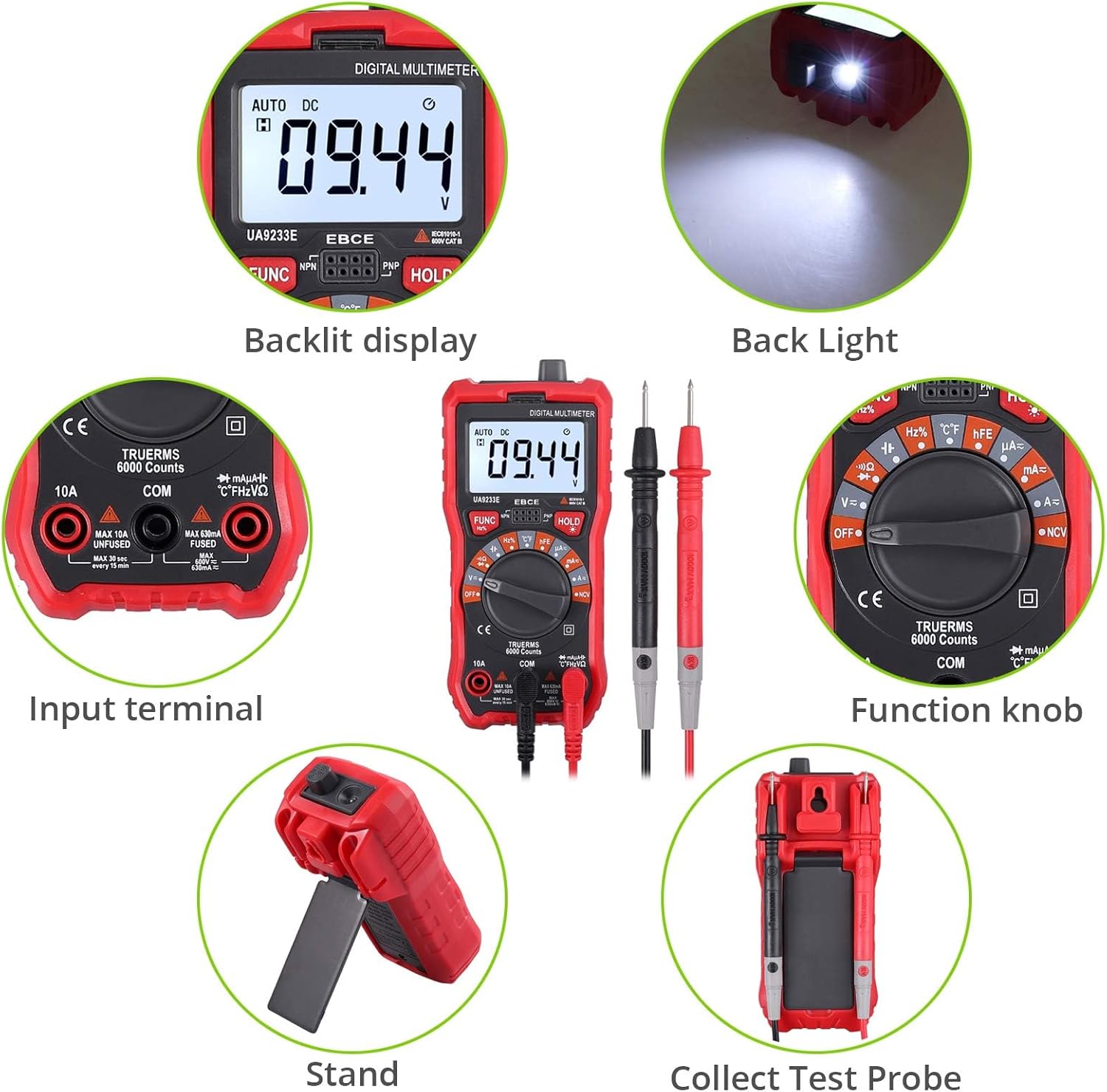
Figure 4.1: Front Panel and Components
Key Components:
- Backlit LCD Display: Shows measurement readings, units, and function indicators.
- Function Knob: Used to select the desired measurement function (e.g., Voltage, Current, Resistance, Temperature, NCV).
- Input Terminals: Sockets for connecting test leads.
- FUNC Button: Toggles between different measurement modes within a single function setting (e.g., AC/DC voltage, diode/continuity).
- HOLD Button: Freezes the current reading on the display.
- Backlight/Flashlight Button: Activates the display backlight and the integrated flashlight.

Figure 4.2: Rear Panel with Support Stand
The multimeter includes a durable protective rubber shell and an integrated support stand for convenient hands-free operation. A hanging hole is also provided for storage.

Figure 4.3: Multimeter Dimensions
5. Setup
5.1 Battery Installation
The multimeter requires one 9V battery (included). To install or replace the battery:
- Ensure the multimeter is turned OFF.
- Locate the battery compartment cover on the back of the meter.
- Remove the screw securing the cover and open it.
- Connect the 9V battery to the battery clips, observing correct polarity.
- Place the battery into the compartment and replace the cover, securing it with the screw.
5.2 Connecting Test Leads
Always connect the black test lead to the 'COM' (Common) terminal. Connect the red test lead to the appropriate input terminal based on the desired measurement:
- VΩHz%°C: For voltage, resistance, frequency, capacitance, diode, continuity, and temperature measurements.
- mAμA: For current measurements up to 600mA.
- 10A: For current measurements up to 10A.
The included alligator clips can be attached to the test leads for hands-free connections.
6. Operating Instructions
This section details how to perform various measurements with your multimeter.
Video 6.1: CAMWAY Digital Multimeter Overview and Basic Operation. This video demonstrates the unboxing, connecting test leads, using the kickstand, selecting functions, measuring DC voltage, and utilizing the NCV feature.
6.1 Voltage Measurement (AC/DC)
- Set the function knob to the 'V=' (DC Voltage) or 'V~' (AC Voltage) position. The meter will auto-range.
- Connect the black test lead to the 'COM' terminal and the red test lead to the 'VΩHz%°C' terminal.
- Connect the test probes in parallel across the circuit or component to be measured.
- Read the voltage value on the LCD display.
6.2 Current Measurement (AC/DC)
Caution: Never connect the meter in parallel with a voltage source when measuring current, as this can blow the fuse or damage the meter.
- Set the function knob to the 'A=' (DC Current) or 'A~' (AC Current) position.
- For currents up to 600mA, connect the black test lead to 'COM' and the red test lead to 'mAμA'. For currents up to 10A, connect the red test lead to '10A'.
- Open the circuit where current is to be measured and connect the test probes in series with the circuit.
- Read the current value on the LCD display.

Figure 6.1: Current Measurement Setup
6.3 Resistance Measurement
- Set the function knob to the 'Ω' (Resistance) position.
- Connect the black test lead to 'COM' and the red test lead to 'VΩHz%°C'.
- Ensure the circuit is de-energized. Connect the test probes across the component to measure its resistance.
- Read the resistance value on the LCD display.
6.4 Capacitance Measurement
- Set the function knob to the 'F' (Capacitance) position.
- Connect the black test lead to 'COM' and the red test lead to 'VΩHz%°C'.
- Ensure the capacitor is fully discharged before measurement. Connect the test probes across the capacitor.
- Read the capacitance value on the LCD display.
6.5 Frequency and Duty Cycle Measurement
- Set the function knob to the 'Hz%' (Frequency/Duty Cycle) position.
- Connect the black test lead to 'COM' and the red test lead to 'VΩHz%°C'.
- Connect the test probes across the signal source.
- Press the 'FUNC' button to toggle between frequency (Hz) and duty cycle (%).
6.6 Diode Test
- Set the function knob to the 'Diode' symbol position.
- Connect the black test lead to 'COM' and the red test lead to 'VΩHz%°C'.
- Connect the red probe to the anode and the black probe to the cathode of the diode. The display will show the forward voltage drop. Reverse the probes; the display should show 'OL' (Open Loop) for a good diode.
6.7 Continuity Test
- Set the function knob to the 'Continuity' symbol position (often shared with Diode or Resistance).
- Connect the black test lead to 'COM' and the red test lead to 'VΩHz%°C'.
- Connect the test probes across the circuit or component. If the resistance is below approximately 50Ω, the buzzer will sound, indicating continuity.
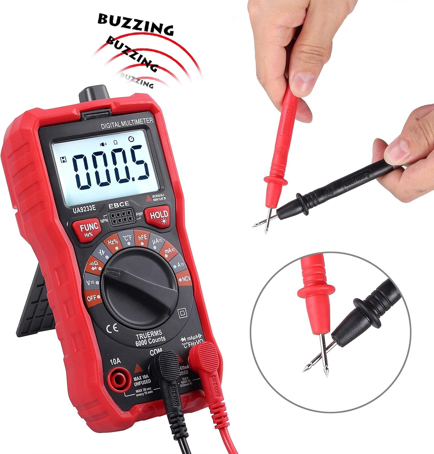
Figure 6.2: Continuity Test
6.8 Temperature Test
- Set the function knob to the '°C/°F' (Temperature) position.
- Connect the K-type thermocouple to the 'VΩHz%°C' and 'COM' terminals, observing polarity.
- Place the tip of the thermocouple on or near the object whose temperature is to be measured.
- Read the temperature value on the LCD display. Press 'FUNC' to switch between Celsius and Fahrenheit.

Figure 6.3: Temperature Measurement
6.9 Non-Contact Voltage (NCV) Detection
- Set the function knob to the 'NCV' position.
- Move the top end of the multimeter close to the conductor or outlet.
- If AC voltage is detected, the meter will emit an audible alarm and the NCV indicator light will flash. The intensity of the alarm and flashing indicates the strength of the electric field.
6.10 HFE Test (Transistor Gain)
- Set the function knob to the 'hFE' position.
- Insert the NPN or PNP transistor leads into the corresponding sockets on the meter.
- Read the hFE value (DC current gain) on the display.
6.11 Data Hold
Press the 'HOLD' button to freeze the current reading on the display. Press it again to release the hold function.
6.12 Backlight and Flashlight
Press the backlight button (often integrated with the HOLD button or a separate button) to turn on the display backlight and the integrated flashlight. Press again to turn them off. This feature is useful in dimly lit environments.
6.13 Auto Power Off
The multimeter is equipped with an auto power-off feature to conserve battery life. If no operation is performed for approximately 15 minutes, the meter will automatically shut down. To reactivate, turn the function knob to OFF and then back to the desired function, or press any button.
7. Maintenance
7.1 General Care
- Keep the meter dry. If it gets wet, wipe it dry immediately.
- Use and store the meter in normal temperature environments. Extreme temperatures can shorten the life of electronic devices.
- Handle the meter gently and carefully. Dropping it can damage the circuit boards or casing.
- Keep the meter away from dust and dirt, which can cause corrosion of electronic components.
- Wipe the meter with a damp cloth occasionally to keep it looking new. Do not use harsh chemicals, cleaning solvents, or strong detergents.
7.2 Fuse Replacement
The multimeter is protected by dual fuses. If the current measurement function fails, the fuse may need replacement. Refer to the specifications for fuse ratings. Fuse replacement should only be performed by qualified personnel.

Figure 7.1: Internal Circuit Board (for reference only, do not open unless qualified)
8. Troubleshooting
If the meter does not function correctly, check the following:
- No display or dim display: Check the battery. Replace if necessary.
- Incorrect readings: Ensure the test leads are correctly inserted into the appropriate terminals for the selected function. Verify the function knob is set to the correct measurement type.
- Current measurement failure: Check the fuse. If blown, replace with a fuse of the correct rating.
- 'OL' (Overload) displayed: The measured value exceeds the meter's range for the selected function. Select a higher range if available, or ensure the input is within the meter's capabilities.
9. Specifications
| Feature | Specification |
|---|---|
| Display | 6000 Counts, Backlit LCD |
| Measurement Type | True RMS Multimeter |
| AC/DC Voltage | Yes |
| AC/DC Current | Yes |
| Resistance | Yes |
| Capacitance | Yes |
| Frequency/Duty Cycle | Yes |
| Diode Test | Yes |
| Continuity Test | Yes (Buzzer at ~50Ω) |
| Temperature Test | -20℃ to 1000℃ / -4℉ to 1832℉ |
| NCV (Non-Contact Voltage) | Yes, with Visual and Audible Alarm |
| HFE Test | Yes |
| Auto Ranging | Yes |
| Data Hold | Yes |
| Auto Power Off | Yes |
| Overload Protection | Yes |
| Fuses | Dual Fuse (600V CAT IV, 1000V CAT III) |
| Power Source | 1 x 9V Battery (included) |
| Material | ABS |
| Dimensions (L x W x H) | 5.91 x 2.68 x 1.97 inches (150 x 68 x 50mm) |
| Item Weight | 7.9 ounces (225 Grams) |
10. Warranty and Support
For warranty information or technical support, please refer to the contact details provided with your purchase or visit the official CAMWAY website. Keep your purchase receipt as proof of purchase.