1. Introduction
This manual provides detailed instructions for the DollaTek TB6560 TB6600 Stepper Motor Driver Board. This driver is designed for controlling two-phase, four-phase, four-wire, or six-wire stepper motors, specifically 42 and 57 series stepper motors up to 4A. It features adjustable current levels, multiple subdivision options, and robust protection circuits to ensure reliable and precise motor control.
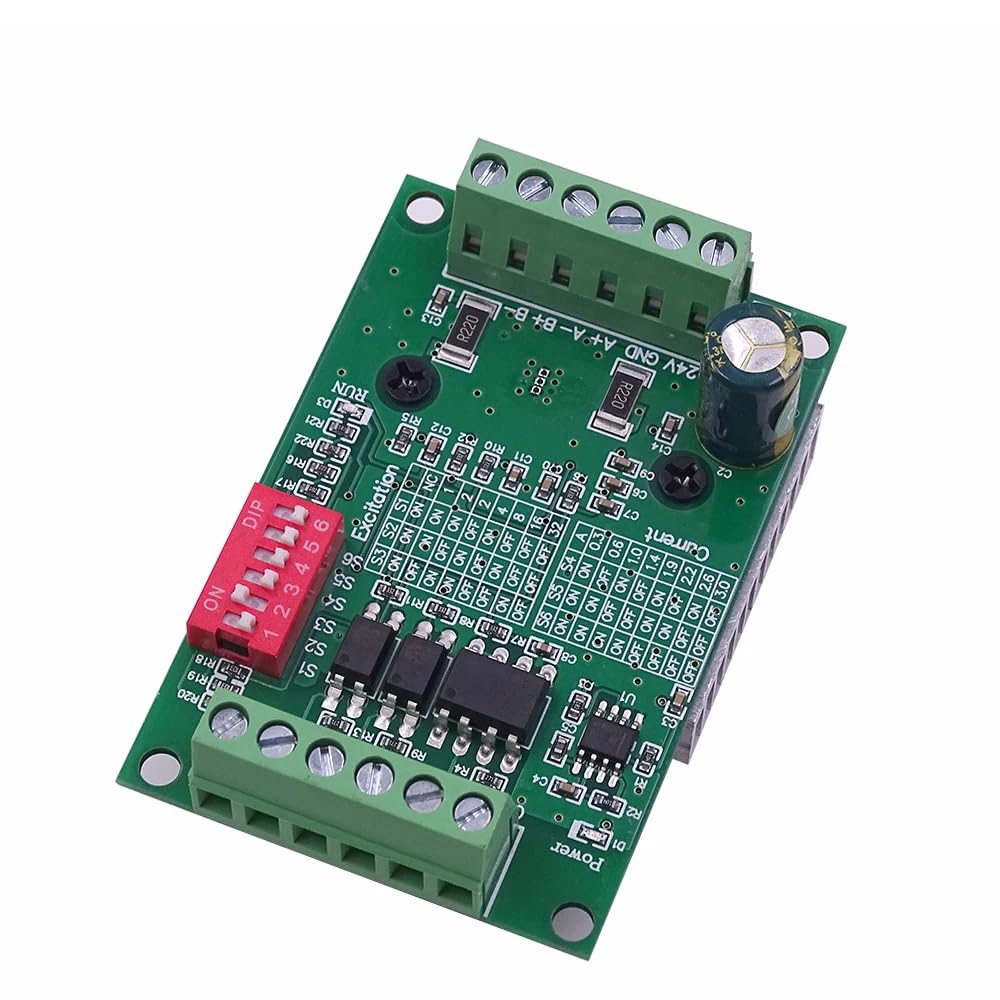
Figure 1: Overview of the DollaTek TB6560 TB6600 Stepper Motor Driver Board.
2. Features
- Adjustable Current: Current level can be adjusted step by step to meet various application requirements.
- Anti-Reverse Connection: Power supply input features anti-reverse connection processing, preventing damage from incorrect polarity.
- High-Speed Optocoupler: Utilizes a high-speed 6N137 optocoupler for high-speed operation without losing steps.
- Integrated Instructions: On-board printed instructions (silkscreen) provide quick reference for settings.
- Efficient Heat Dissipation: Equipped with a thick and densely finned heatsink for effective thermal management.
- Wide Operating Voltage: Supports DC 10V-35V input.
- Advanced Protection: Includes low-voltage shutdown, overheating shutdown, and overcurrent protection circuits.
- Motor Compatibility: Suitable for two-phase, four-phase, four-wire, or six-wire 42 and 57 series stepper motors up to 4A.
- Automatic Half-Current: Features an automatic half-current function.
- Multiple Subdivisions: Supports full step, half step, 1/4 step, 1/8 step, 1/16 step, and 1/32 step subdivisions.
3. Specifications
| Specification | Value |
|---|---|
| Brand | DollaTek |
| Model | TB6560 TB6600 |
| Operating Voltage | DC 10V-35V (DC24V recommended) |
| Rated Maximum Output Current | 3A |
| Motor Compatibility | 2-phase / 4-phase / 4-wire / 6-wire stepper motors (42, 57 series up to 4A) |
| Subdivision Settings | Full, 1/2, 1/4, 1/8, 1/16, 1/32 step |
| Protection Circuits | Low-voltage shutdown, overheating shutdown, overcurrent protection |
4. Setup
4.1 Power Connection
Connect the power supply to the terminal block labeled +24V and GND. The operating voltage range is DC 10V to 35V. For optimal performance and stability, a DC24V switching power supply is recommended. The board is designed with anti-reverse connection protection, which helps prevent damage if the power polarity is accidentally reversed.
4.2 Motor Connection
Connect your stepper motor to the terminal blocks labeled A+, A-, B+, B-. This driver supports two-phase, four-phase, four-wire, or six-wire stepper motors. Ensure correct wiring according to your motor's specifications. For six-wire motors, the common wires should be left unconnected or wired as per specific motor requirements for unipolar/bipolar conversion.

Figure 2: Top view of the driver board, highlighting power and motor connection terminals.
4.3 Control Signal Connection
Connect your control signals (Pulse, Direction, Enable) to the terminal blocks labeled CLK+, CLK-, CW+, CW-, EN+, EN-. The driver uses a high-speed 6N137 optocoupler for signal isolation, ensuring reliable communication and preventing noise interference. Ensure your control signals are compatible with the driver's input requirements.

Figure 3: Angled view of the driver board, showing control signal input terminals.
5. Operating
The DollaTek TB6560 TB6600 driver board features DIP switches for configuring current settings and micro-stepping (subdivision) modes. Refer to the silkscreen markings on the board for specific switch positions.
5.1 Current Adjustment
The output current can be adjusted using the DIP switches labeled Current. These switches allow you to set the peak output current to match your stepper motor's rated current. Adjust the current in steps to prevent motor overheating while ensuring sufficient torque.
5.2 Subdivision Settings (Micro-stepping)
The subdivision (micro-stepping) settings are controlled by the DIP switches labeled Excitation. You can select from full step, half step, 1/4 step, 1/8 step, 1/16 step, and 1/32 step modes. Higher subdivision settings result in smoother motor movement and reduced resonance but may require higher pulse rates from your controller.
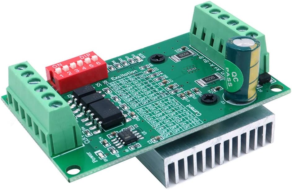
Figure 4: Close-up view of the DIP switches for current and excitation (subdivision) settings.
5.3 Automatic Half-Current Function
The driver includes an automatic half-current function. When the motor is idle (no step pulses received for a certain period), the driver automatically reduces the current to the motor windings. This feature helps to reduce motor heating and power consumption when the motor is not actively moving.
6. Maintenance
The DollaTek TB6560 TB6600 driver board is designed for durability and reliability. Regular maintenance is minimal but important for long-term performance.
- Heat Dissipation: The board features a thick, densely finned heatsink for efficient heat dissipation. Ensure adequate airflow around the driver, especially during continuous operation or when driving high-current motors. Avoid obstructing the heatsink.
- Cleanliness: Keep the board free from dust, debris, and moisture. Use a soft, dry brush or compressed air to clean the board if necessary.
- Connections: Periodically check all wire connections to ensure they are secure and free from corrosion. Loose connections can lead to intermittent operation or damage.

Figure 5: Bottom view of the driver board, illustrating the heatsink for thermal management.
7. Troubleshooting
If you encounter issues with your DollaTek TB6560 TB6600 stepper motor driver, consider the following troubleshooting steps:
- Motor Not Moving:
- Verify power supply voltage is within DC 10V-35V and correctly connected.
- Check motor wiring for correct phase connections (A+, A-, B+, B-).
- Ensure control signals (CLK, CW, EN) are correctly connected and active.
- Confirm DIP switch settings for current and subdivision are appropriate for your motor.
- Motor Overheating:
- Reduce the output current setting using the DIP switches.
- Ensure adequate ventilation around the driver board and motor.
- Check if the motor is overloaded.
- Erratic Motor Movement or Lost Steps:
- Check for loose connections in motor or control signal wiring.
- Ensure the control signal frequency is not too high for the driver or motor.
- Verify the power supply is stable and can provide sufficient current.
- The driver has built-in overcurrent and overheating protection; if these trigger, the motor may stop or behave erratically. Address the root cause (e.g., reduce current, improve cooling).
8. Warranty and Support
The DollaTek TB6560 TB6600 Stepper Motor Driver Board typically comes with a 1-year manufacturer warranty. For technical support or warranty claims, please contact your retailer or the manufacturer, DollaTek, directly. Ensure you have your purchase details and product model information available when seeking support.