Introduction
This manual provides essential information for the safe and effective installation, operation, and maintenance of your uxcell Red Indicator Light. This indicator light is designed for use in various electrical control panels, HVAC systems, and DIY projects, providing visual status indication with its bright red LED.
Safety Information
- Always disconnect power before installation, maintenance, or troubleshooting to prevent electrical shock.
- Ensure all wiring connections are secure and comply with local electrical codes.
- Do not exceed the specified voltage (AC/DC 12V).
- Handle components carefully to avoid damage.
- This product is intended for indoor use or in environments protected from direct moisture unless otherwise specified.
Product Overview
The uxcell Red Indicator Light features a durable construction with a bright LED for clear visual signaling. It is designed for panel mounting with a standard 22mm hole.
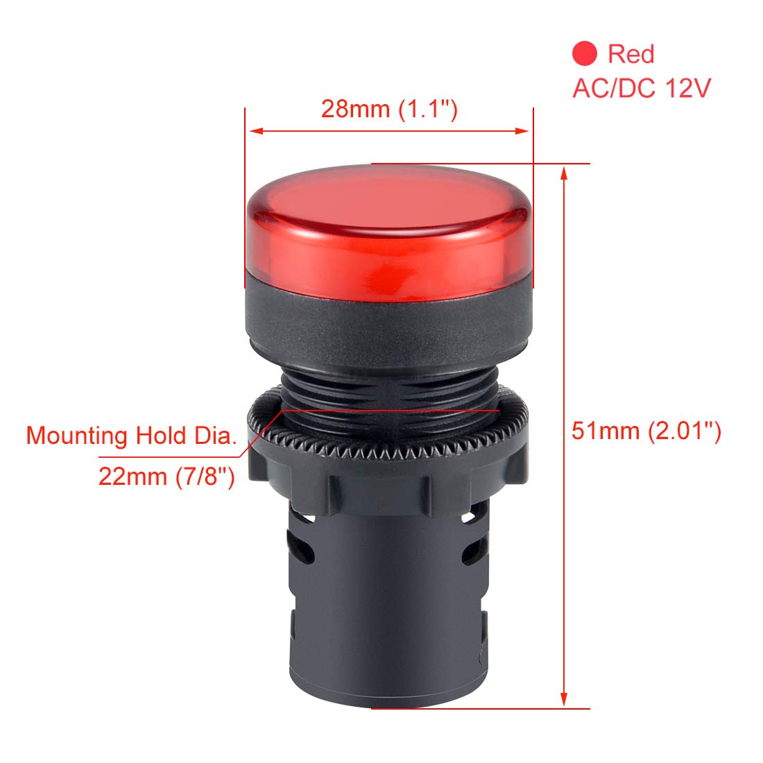
This diagram illustrates the key dimensions of the uxcell Red Indicator Light. It has a head diameter of 28mm (1.1 inches), an overall length of 51mm (2.01 inches), and requires a 22mm (7/8 inch) mounting hole.

This image displays the internal components of the indicator light, with the red lens removed, revealing the LED module inside the housing.

The included dust cap helps protect the internal electrical connections from dust and debris, enhancing the longevity and reliability of the indicator light.

This graphic highlights key features: the AD16-22D/S model designation, use of LED chips for illumination, high brightness output, and a standard 22mm mounting hole.
Specifications
| Model Number | a18033000ux0461 |
| Color | Red |
| Voltage | AC/DC 12V |
| Mounting Type | Panel Mount |
| Mounting Hole Diameter | 22mm (7/8") |
| Max Panel Thickness | ≤6mm (0.24") |
| Depth Behind Panel | 37mm (1.46") |
| Light Source Type | Light Emitting Diode (LED) |
| Material | Copper (terminals), Plastic (housing) |
| Item Weight | Approximately 0.01 Ounces |

A comprehensive dimension diagram showing the head diameter (Φ28mm), head length (13mm), depth behind panel (37mm), overall length (51mm), mounting hole diameter (Φ22mm), and maximum panel thickness (≤6mm).
Setup and Installation
- Prepare Mounting Hole: Drill a 22mm (7/8 inch) diameter hole in your panel. Ensure the panel thickness does not exceed 6mm (0.24 inches).
- Insert Indicator Light: Insert the indicator light into the drilled hole from the front of the panel.
- Secure with Locking Nut: Thread the panel locking nut onto the indicator light from the back of the panel and tighten it securely to hold the light in place.
- Wiring Connections:
- The indicator light uses screw-clamp terminals for electrical connections.
- Connect your AC/DC 12V power supply wires to these terminals. The indicator light is non-polarized, meaning the connection order of positive and negative wires does not affect its function.
- Ensure wires are stripped to an appropriate length and inserted fully into the terminals before tightening the screws. Avoid over-tightening, as this may damage the terminal mechanism.
- Note that the depth behind the panel is 37mm. Ensure adequate space for wiring and connections, especially in confined enclosures.
- Install Dust Cap: If applicable, snap the dust cap onto the rear of the indicator light to protect the terminals from dust and debris.
Operating Instructions
Once properly installed and wired, the uxcell Red Indicator Light will illuminate when power (AC/DC 12V) is supplied to its terminals. The LED will emit a steady red light, indicating the status of the circuit or equipment it is connected to.

This image demonstrates the uxcell Red Indicator Light in its illuminated state, showcasing its bright red light output.
Maintenance
- Periodically inspect the indicator light for any physical damage or loose connections.
- Clean the lens with a soft, dry cloth if dust or dirt accumulates, ensuring clear visibility. Do not use abrasive cleaners.
- Ensure the dust cap (if installed) remains securely in place to protect the wiring terminals.
Troubleshooting
- Indicator Light Does Not Illuminate:
- Verify that the power supply (AC/DC 12V) is active and correctly connected to the indicator light terminals.
- Check for loose or faulty wiring connections. Re-secure any loose wires.
- Ensure the voltage supplied matches the product's specification (12V).
- Inspect the LED for any visible damage.
- Intermittent Illumination:
- Check for loose wiring connections at the terminals or within the circuit.
- Ensure stable power supply.
Warranty and Support
For warranty information or technical support, please refer to the product packaging or contact uxcell customer service through their official channels. Keep your purchase receipt for any warranty claims.


