1. Product Overview
The DIYhz EC11 Rotary Encoder with Switch is a versatile electronic component designed for precise digital input. It combines the functionality of a rotary encoder, which detects rotational movement, with an integrated push-button switch. This makes it ideal for applications requiring both rotational input (e.g., volume control, menu navigation) and a momentary switch action (e.g., selection, mute).
This package includes 10 units of the EC11 Rotary Encoder, each featuring a 20MM shaft, suitable for various electronic projects and repairs.

Figure 1: Overview of the 10-pack EC11 Rotary Encoder with Switch. Each encoder features a metal shaft and a green base with multiple pins for electrical connection.
2. Key Features
- Quantity: 10 x EC11 Rotary Encoder with Switch (20MM shaft).
- Rated Voltage: DC 5V.
- Shaft Movement Direction: Action Type: Momentary (for the switch function).
- Material: Plastic and Metal construction.
- Color: Blue and Silver Tone (referring to the main body and shaft).
3. Specifications
| Rated Voltage | DC 5V |
| Maximum Operating Current (Resistive Load) | Each lead: 0.5mA (Max 5mA; Min 0.5mA) |
| Common Lead Current | 1mA (Max 10mA; Min 0.5mA) |
| Shaft Length | 20MM |
| Dimensions (Package) | 4 x 1.6 x 0.4 inches |
| Item Weight | 2.39 ounces |
| Model Number | 10048 |

Figure 2: Electrical parameters and waveform diagram for the EC11 Rotary Encoder. This diagram illustrates the internal circuitry and the expected output signals during rotation.
4. Safety Precautions
To ensure the longevity and proper functioning of your EC11 Rotary Encoders, please observe the following precautions:
- Storage: Avoid storing the products in environments with high temperature, high humidity, or corrosive gases. Such conditions can degrade the components and affect performance.
- Moisture Exposure: Do not allow the product to come into contact with water or other liquids. Moisture can cause short circuits, abnormal output waveforms, and permanent damage to the encoder.
- Handling: Handle with care. While the product is robust, excessive force or improper handling can bend pins or damage internal mechanisms.
5. Setup and Installation
The EC11 Rotary Encoder is designed for integration into electronic circuits. Proper connection is crucial for its operation.
5.1 Pinout and Connections
The encoder typically has multiple pins for connection to a microcontroller or other digital logic. Refer to the provided diagrams for specific pin assignments (Terminal A, Terminal B, Terminal C for encoder, and SW1, SW2 for the switch).
- Encoder Pins (A, B, C): These pins provide the quadrature output signals that indicate rotation direction and steps. Terminal C is typically connected to ground.
- Switch Pins (SW1, SW2): These pins connect to the integrated push-button switch. When the shaft is pressed, the switch closes, creating a momentary connection.
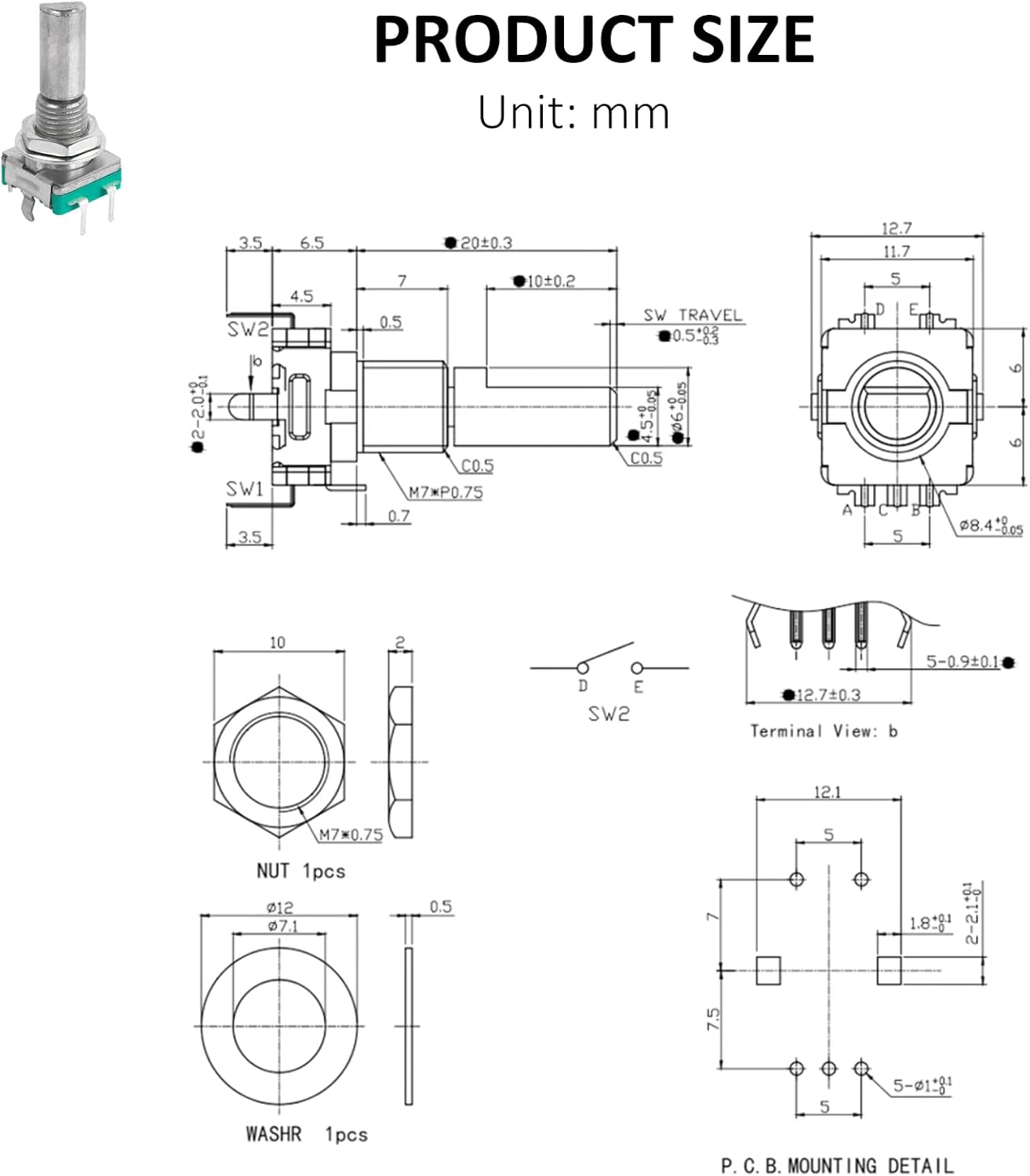
Figure 3: Detailed dimensional drawing of the EC11 Rotary Encoder, showing physical measurements in millimeters and pin configurations. This is essential for PCB design and mechanical integration.
5.2 Mounting
The encoder is designed for panel mounting using the included nut and washer. Ensure the mounting hole size on your panel matches the shaft diameter for a secure fit.

Figure 4: EC11 Rotary Encoder with its accompanying nut and washer, used for secure panel mounting.
6. Operating Principles
The EC11 Rotary Encoder operates by generating a series of electrical pulses as its shaft is rotated. These pulses are typically read by a microcontroller to determine the direction and magnitude of rotation.
- Rotary Function: As the shaft turns, the internal contacts generate two out-of-phase square wave signals (often referred to as A and B phases). By monitoring the leading or trailing edges of these signals relative to each other, the direction of rotation (clockwise or counter-clockwise) can be determined.
- Switch Function: Pressing the shaft activates a momentary push-button switch. This switch provides a simple ON/OFF signal, useful for selection, confirmation, or toggling functions.
The waveform diagram (Figure 2) illustrates the typical output signals (Code-OFF area: voltage is 3.5V or more; Code-ON area: voltage is 1.5V or less).
7. Maintenance
EC11 Rotary Encoders are generally low-maintenance components. However, adhering to the following guidelines can help ensure their long-term reliability:
- Cleanliness: Keep the encoder free from dust, dirt, and debris, especially around the shaft and internal mechanism. Use a soft, dry brush or compressed air for cleaning.
- Environmental Control: As mentioned in safety precautions, avoid exposure to extreme temperatures, high humidity, and corrosive substances.
- Physical Inspection: Periodically inspect the pins for any signs of bending or corrosion. Ensure the mounting nut remains tight.
8. Troubleshooting
If you encounter issues with your EC11 Rotary Encoder, consider the following common problems and solutions:
- Incorrect Rotation Detection (Polarity): Some encoders may operate with opposite polarity compared to others. If clockwise rotation decrements instead of increments, or vice-versa, check your software logic or consider reversing the A and B phase connections if your application allows.
- Skipping Clicks/Unreliable Rotation:
- Debouncing: Rotary encoders often require software debouncing to filter out spurious signals caused by mechanical contact bounce. Ensure your microcontroller code implements proper debouncing routines.
- Loose Connections: Verify all electrical connections are secure and properly soldered.
- Bent Pins: Inspect pins for damage. Bent pins can lead to intermittent contact. Carefully straighten them if necessary, but be aware that repeated bending can weaken the metal.
- Environmental Factors: Ensure the encoder is not exposed to excessive vibration or electromagnetic interference, which can affect signal integrity.
- Switch Not Responding:
- Connection Check: Verify the switch pins (SW1, SW2) are correctly wired to your circuit.
- Software Logic: Ensure your software is correctly polling or interrupting on the switch input.
- No Output:
- Power Supply: Confirm the encoder is receiving the correct DC 5V power.
- Ground Connection: Ensure the common pin (Terminal C) is properly grounded.
- Damaged Unit: If all connections and software logic are correct, the unit may be faulty.
9. Warranty and Support
Specific warranty details for the DIYhz EC11 Rotary Encoder are not provided in this manual. For information regarding warranty coverage, returns, or technical support, please refer to the seller's policies on the platform where the product was purchased or contact DIYhz directly through their official channels.
You can often find support information on the product listing page or by visiting the DIYhz brand store on Amazon: DIYhz Amazon Store.


