1. Introduction
The CNYST ETCR9100 is a high and low voltage clamp current meter designed for precise measurement of AC leakage current and general AC current. It is capable of measuring currents up to 600A and is suitable for line tests below 60kV when used with its insulated rods. This instrument incorporates advanced features such as peak hold, data retention, and data storage, ensuring reliable and accurate measurements in various industrial and scientific applications.
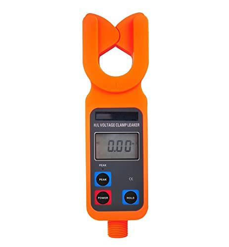
Figure 1.1: Front view of the ETCR9100 Clamp Current Meter, showing the LCD display and control buttons.
2. Product Components
The ETCR9100 system includes the main clamp meter unit and a set of five high-voltage insulated rods, along with a carrying case for transport and storage.
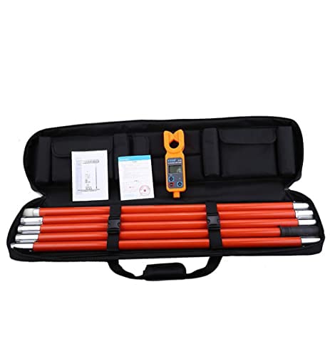
Figure 2.1: The ETCR9100 Clamp Current Meter kit, including the meter, insulated rods, and carrying case.
2.1 Main Unit Features
- Clamp Jaw: Φ33mm opening for current clamping.
- LCD Display: 47mm x 28.5mm with backlight for clear readings.
- Control Buttons: PEAK, POWER, HOLD for various functions.
- Battery Compartment: Located at the rear for 4x 1.5V (AAA) batteries.
2.2 Insulated Rods
The system includes five sections of insulated rods, each 1 meter in length and Φ32mm in diameter. These rods are designed for high insulation, moisture resistance, high temperature resistance, impact resistance, bending resistance, and detachability, enabling safe measurements on high-voltage lines.
3. Setup and Assembly
3.1 Battery Installation
- Locate the battery compartment on the rear of the clamp meter.
- Open the battery compartment cover.
- Insert four 1.5V AAA (7#) batteries, ensuring correct polarity.
- Close the battery compartment cover securely.
Note: Batteries are not included in the package and must be purchased separately.
3.2 Assembling the Insulated Rods
For high-voltage measurements, assemble the insulated rods by screwing them together securely. Ensure all connections are tight before use. The number of rod sections used will depend on the voltage level and required reach.
4. Operating Instructions
4.1 Power On/Off
- Press the POWER button to turn the meter on.
- The meter will automatically shut down after approximately 15 minutes of inactivity to conserve battery life.
- To manually turn off, press and hold the POWER button.
4.2 Current Measurement (AC Leakage and General Current)
- Ensure the meter is powered on.
- Open the clamp jaw by pressing the trigger.
- Position the conductor to be measured within the clamp jaw. Ensure the jaw is fully closed around the conductor.
- The meter will automatically identify the frequency (50Hz/60Hz) and shift to the appropriate range.
- Read the AC current or leakage current value displayed on the LCD.
Measurement method: Clamp CT, non-contact measurement, integral method.
4.3 High Voltage Line Testing (Below 60kV)
When measuring current on lines below 60kV, attach the assembled insulated rods to the clamp meter. Maintain a safe distance and follow all safety protocols for high-voltage environments. The non-contact measurement method allows for safe operation.
4.4 Peak Hold Function
- In test mode, press the PEAK button.
- The "PEAK" lamp on the display will illuminate, indicating the function is active.
- The meter will automatically hold and display the highest measured value.
- Press PEAK again to exit peak hold mode.
4.5 Data Hold Function
- During a measurement, press the HOLD key.
- The "HOLD" symbol will appear on the display, indicating the current reading is frozen.
- Press HOLD again to release the data and resume live measurement.
4.6 Data Storage and Review
- The meter can store up to 99 groups of data.
- Specific instructions for saving data are typically detailed in the full product manual.
- To review stored data, look for the "MR" symbol on the display, which indicates that data can be scrolled up and down.
5. Maintenance
5.1 Cleaning
Wipe the meter's exterior with a soft, dry cloth. Do not use abrasive cleaners or solvents. Ensure the meter is powered off before cleaning.
5.2 Storage
When not in use for extended periods, remove the batteries to prevent leakage. Store the meter and its accessories in the provided carrying case in a dry environment with temperatures between -10 °C and 60 °C and relative humidity below 70%.
5.3 Battery Replacement
Replace batteries when the low voltage alarm activates (battery voltage below 4.8V). Refer to Section 3.1 for battery installation instructions.
6. Troubleshooting
6.1 Low Battery Indication
If the battery voltage drops below 4.8V, a voltage alarm will activate. Replace the four 1.5V AAA batteries immediately to ensure accurate measurements and proper operation.
6.2 "OLA" Display (Overload Indication)
The "OLA" symbol on the display indicates an overrange overflow condition. This means the measured current exceeds the meter's maximum range of 600A. Disconnect the meter from the circuit and ensure the current is within the specified measurement range before attempting further measurements.
6.3 No Display or Erratic Readings
- Check battery installation and ensure batteries are fresh.
- Verify the clamp jaw is fully closed around the conductor.
- Ensure the operating environment is within specified conditions (-20°C to 40°C; 80% RH or less).
- If issues persist, contact customer support.
7. Technical Specifications
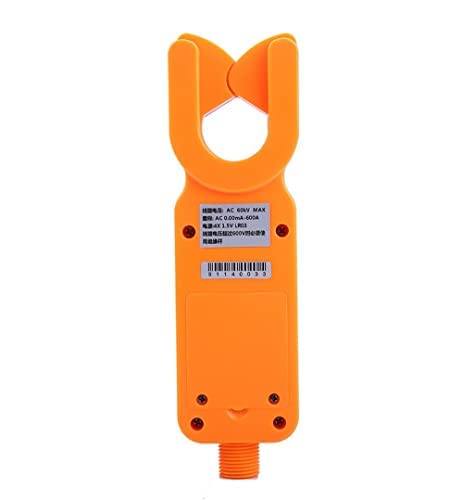
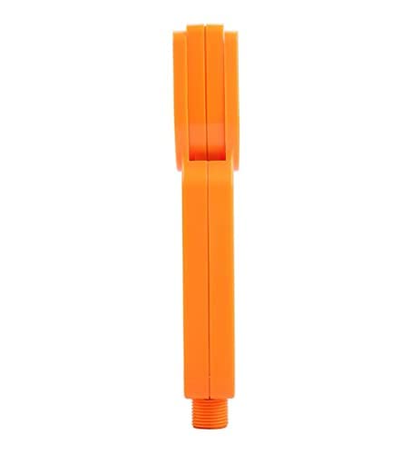
Figure 7.1: Rear and side views of the ETCR9100 Clamp Current Meter, showing product labels and profile.
| Parameter | Specification |
|---|---|
| Function | High and low voltage AC leakage current, current measurement |
| Clamp Size | Φ33mm |
| LCD Size | 47mm x 28.5mm (with backlight) |
| Range | AC 0.00mA ~ 600A |
| Resolution | 0.01mA |
| Accuracy | ±1%rdg±5dgt (23°C±5°C, 80%rh or less) |
| Data Storage | 99 Groups |
| Automatic Shutdown | Approximately 15 minutes of inactivity |
| Working Environment | -20°C ~ 40°C; 80% rh |
| Storage Environment | -10°C ~ 60°C; 70% rh below |
| Structure | Anti-drip II |
| Measurement Method | Clamp CT, non-contact measurement, integral method |
| Frequency | 50Hz, 60Hz automatic identification |
| Shift | Automatic shifting |
| Line Voltage Test | Below 60KV (with 5 sections insulation rod operation) |
| Measurement Time | 0.5 seconds/time |
| Voltage Alarm | When battery voltage is lower than 4.8V |
| Insulation Rod Size | Φ32mm, 1m/section (5 sections) |
| Insulation Strength | Rod to detector shell: AC 100kV/rms; Detector shell to iron core: AC1000V/rms |
| Clamp Meter Quality (Weight) | Detector: approx. 335g; Total instrument mass: approx. 7Kg (with insulation rod) |
| Power Supply | DC 6V (4x 1.5V AAA batteries) |
| Clamp Meter Size (L x W x T) | 245mm x 68mm x 40mm |
| Product Dimensions (Packaged) | 43.31 x 3.94 x 9.84 inches; 15.43 Pounds |
| Manufacturer | CNYST |
| ASIN | B07CWPRR66 |
| UPC | 665059472101 |
8. Warranty and Support
Information regarding the specific warranty period or terms for the CNYST ETCR9100 High and Low Voltage Clamp Current Meter is not available in the provided product data. For warranty claims, technical support, or service inquiries, please contact the manufacturer directly.
Manufacturer: CNYST
For more information, you may visit the CNYST Store on Amazon.
9. Official Product Videos
No official product videos from the seller were found in the provided data for the CNYST ETCR9100 High and Low Voltage Clamp Current Meter.