1. Introduction
This manual provides essential information for the proper use, installation, and maintenance of the Aexit 5W 3.9 Ohm Wirewound Radial Ceramic Cement Resistors. These resistors are designed for applications requiring good heat resistance, low temperature coefficient, high load power, and high insulating capacity. Please read this manual thoroughly before using the product.
2. Product Overview
The Aexit 5W 3.9 Ohm Wirewound Radial Ceramic Cement Resistors are passive electronic components used to limit current flow, adjust signal levels, divide voltages, bias active elements, and terminate transmission lines. They are characterized by their ceramic body, cement coating, and radial lead design, making them suitable for various electronic circuits.
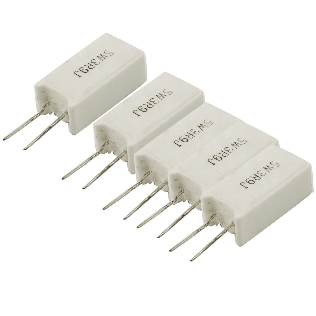
Figure 1: A single Aexit 5W 3.9 Ohm Wirewound Radial Ceramic Cement Resistor. This image shows the white ceramic body, the radial leads for through-hole mounting, and the overall compact design of the component.
Key Features:
- High Power Rating: 5 Watts, suitable for applications requiring significant power dissipation.
- Precise Resistance: 3.9 Ohm with a tolerance of ±5%.
- Durable Construction: Ceramic body with cement coating for enhanced heat resistance and insulation.
- Radial Leads: Designed for easy through-hole mounting on printed circuit boards.
3. Specifications
| Parameter | Value |
|---|---|
| Product Name | Cement Resistor |
| Body Material | Ceramic, Cement |
| Power Rating | 5W |
| Resistance | 3.9 Ohm |
| Tolerance | ±5% |
| Body Size (Approx.) | 25 x 13 x 9mm (1'' x 0.5'' x 0.35'') (L * W * H) |
| Pin Size (Approx.) | 11 x 0.7mm (0.43'' x 0.03'') (L*D) |
| Pin Spacing | 5mm (0.2'') |
| Color | White |
| Weight (per unit) | Approximately 6.6g (33g for 5 units) |
4. Setup and Installation
These resistors are designed for through-hole mounting on printed circuit boards (PCBs) or for use in breadboards and prototyping. Proper installation is crucial for optimal performance and safety.
- Identify Correct Value: Before installation, verify that the resistor's value (3.9 Ohm) and power rating (5W) match your circuit design requirements.
- Lead Bending: Carefully bend the radial leads to fit the spacing on your PCB or breadboard. Avoid bending the leads too close to the resistor body to prevent damage.
- Insertion: Insert the resistor leads into the designated holes on the PCB or breadboard. Ensure the resistor body is flush with the board surface if required by your design.
- Soldering (for PCBs): If soldering, ensure proper soldering techniques are used. Heat the lead and pad simultaneously, apply solder, and allow it to flow evenly. Avoid excessive heat, which can damage the resistor or PCB. Trim excess lead length after soldering.
- Polarity: Resistors are generally non-polar components, meaning they can be installed in either orientation. However, always double-check your circuit diagram for any specific requirements.
Safety Note: Always disconnect power from the circuit before installing or removing components. Wear appropriate personal protective equipment (PPE) such as safety glasses when soldering.
5. Operating Principles
A resistor's primary function is to oppose the flow of electric current. When current passes through a resistor, it dissipates energy in the form of heat, according to Joule's Law (P = I²R or P = V²/R). The 5W power rating indicates the maximum amount of power the resistor can safely dissipate without being damaged.
These cement resistors are particularly suited for applications where heat dissipation is a concern, such as:
- Current limiting in power supplies.
- Voltage division in high-power circuits.
- Load resistors in testing environments.
- Applications in TV sets, audio equipment (sound prescalers), and industrial meters where stable performance under varying temperatures is required.
Ensure that the actual power dissipated by the resistor in your circuit does not exceed its 5W rating to prevent overheating and component failure.
6. Maintenance
Aexit cement resistors are passive components and generally require minimal maintenance. However, following these guidelines can help ensure their longevity and reliable performance:
- Environmental Conditions: Store and operate resistors in a clean, dry environment, free from excessive dust, moisture, and corrosive gases.
- Temperature Management: Ensure adequate ventilation around the resistors, especially in high-power applications, to prevent excessive heat buildup. Operating within specified temperature ranges is crucial.
- Physical Inspection: Periodically inspect resistors for any signs of physical damage, such as cracks in the cement coating, discoloration (indicating overheating), or damaged leads.
- Cleaning: If necessary, gently clean the resistor body with a soft, dry brush or a cloth lightly dampened with isopropyl alcohol. Ensure the circuit is powered off and completely dry before re-energizing.
7. Troubleshooting
If you encounter issues with your circuit involving these resistors, consider the following troubleshooting steps:
| Problem | Possible Cause | Solution |
|---|---|---|
| Resistor appears burnt or discolored. | Excessive power dissipation (exceeding 5W rating). | Verify circuit design; ensure power dissipation is within limits. Consider using a higher wattage resistor if necessary. Check for short circuits elsewhere in the circuit. |
| Incorrect resistance reading. | Damaged resistor, incorrect component installed, or measurement error. | Remove resistor from circuit and measure its resistance with a multimeter. Replace if damaged or incorrect. Ensure multimeter is functioning correctly. |
| Circuit not functioning as expected. | Poor solder joint, incorrect wiring, or other component failure. | Inspect solder joints for cold joints or bridges. Double-check wiring against the schematic. Test other components in the circuit. |
8. Warranty Information
Aexit products are manufactured to high standards. While specific warranty terms may vary by region and distributor, Aexit typically provides a limited warranty against defects in materials and workmanship for a period of one year from the date of purchase. This warranty does not cover damage resulting from improper installation, misuse, unauthorized modification, or operation outside the specified parameters.
Please retain your proof of purchase for any warranty claims.
9. Customer Support
For technical assistance, product inquiries, or support regarding Aexit 5W 3.9 Ohm Wirewound Radial Ceramic Cement Resistors, please contact your local distributor or visit the official Aexit website for contact information.
Online Resources: www.aexit.com (Note: This is a placeholder URL, please refer to the actual manufacturer's website for support.)