ANMBEST AMS1117-3.3
ANMBEST AMS1117-3.3 DC-DC Voltage Regulator Module Instruction Manual
1. Introduction
This instruction manual provides essential information for the safe and effective use of the ANMBEST AMS1117-3.3 DC-DC Voltage Regulator Step Down Power Supply Buck Module. This module is designed to convert an input voltage range of 4.75V-12V DC into a stable 3.3V DC output, with a maximum output current of 800mA. It is suitable for various electronic projects requiring a regulated 3.3V power supply.
2. Features
- Positive Voltage Regulator Step Down Power Supply Module.
- Supports DC 4.75V-12V input.
- Provides fixed 3.3V DC output.
- Maximum output current: 800mA.
- Simple dual-panel design with 2-pin single row pins for easy input/output connection.
- Integrated overheat shutdown circuit for overload and over-temperature protection.
3. Specifications
| Parameter | Value |
|---|---|
| Input Voltage | DC 4.75V - 12V |
| Output Voltage | 3.3V (Fixed) |
| Output Current | 800mA (Max) |
| Line Adjustment Rate | 0.2% (Max) |
| Load Regulation | 0.4% (Max) |
| Operating Junction Temperature Range | -40 to 125°C |
| Storage Temperature | -65 to 150°C |
| Voltage Difference | 1.3V (Max) |
| Current Limit | 900 ~ 1500mA |
| Quiescent Current | 10mA (Max) |
| Ripple Suppression | 60dB (Min) |
| Module Size | 8.6mm x 12.33mm |
4. Safety Precautions
- Do not exceed the specified operating voltage (4.75V-12V DC input), as this can damage the module.
- Exceeding the maximum allowable power consumption will result in excessive chip temperature, potentially leading to damage or reduced lifespan.
- Ensure correct polarity when connecting the input power. Reversing polarity will result in a short circuit and damage the module.
- Handle the module with care to avoid electrostatic discharge (ESD) damage.
5. Setup and Connection
The AMS1117-3.3 module features three main pins for connection: VIN (Input Voltage), GND (Ground), and OUT (Output Voltage). Refer to the connection diagram below for proper wiring.

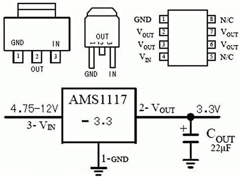
- Input Connection (VIN): Connect the positive terminal of your DC power source (4.75V-12V) to the 'VIN' pin on the module.
- Ground Connection (GND): Connect the negative terminal of your DC power source to the 'GND' pin. Ensure this is a common ground for both input and output.
- Output Connection (OUT): The regulated 3.3V DC output will be available between the 'OUT' pin (positive) and the 'GND' pin (negative). Connect your 3.3V load to these pins.
- Verification: Before connecting sensitive components, it is recommended to verify the output voltage using a multimeter to ensure it is stable at 3.3V.
Visual Guide: USB Power to 3V Down Converter
This video demonstrates a practical application of a similar buck converter, showing how to convert USB power to a lower voltage, which can be adapted for the AMS1117-3.3 module to provide 3.3V.
6. Operating Instructions
Once properly connected, the AMS1117-3.3 module will automatically regulate the input voltage to a stable 3.3V output. No further adjustments are required as this is a fixed voltage regulator. Ensure your load does not draw more than 800mA to maintain stable operation and prevent overheating.
Visual Guide: AMS1117 LDO Buck Module Overview
This video provides an overview of the AMS1117 LDO buck module, demonstrating its functionality and how it can be used in various electronic setups. It covers both fixed and adjustable output versions, offering valuable context for understanding the 3.3V fixed output module.
7. Applications
The AMS1117-3.3 module is versatile and can be used in various electronic projects, including:
- SCM (Single-Chip Microcomputer) project designs requiring a 3.3V power supply.
- Powering 3.3V low power consumption microcontrollers (MCUs).
- FPGA/CPLD PLD Programmable Logic Systems.
- ARM7, ARM9, ARM11, STM32 development boards.
- High-efficiency linear regulator applications.
- Active power regulator and battery charger circuits.
8. Troubleshooting
- No Output Voltage: Check input voltage (VIN) to ensure it is within the 4.75V-12V range. Verify all connections for proper contact and polarity.
- Incorrect Output Voltage: Ensure the module is correctly wired. If the output is significantly off, the module may be damaged.
- Overheating: Reduce the load current to ensure it does not exceed 800mA. Verify that the input voltage is not excessively high, which can increase power dissipation. Ensure adequate ventilation around the module.
- Module Damage: If the module shows signs of physical damage, burning, or does not function after verifying connections and power, it may be faulty and require replacement.
9. Maintenance
The AMS1117-3.3 voltage regulator module requires minimal maintenance. To ensure optimal performance and longevity:
- Keep the module clean and free from dust, moisture, and corrosive substances.
- Avoid physical stress or impact that could damage the components or solder joints.
- Ensure proper heat dissipation, especially when operating at higher input voltages or near the maximum current limit.
10. Warranty and Support
For warranty information, technical support, or any inquiries regarding your ANMBEST AMS1117-3.3 Voltage Regulator Module, please refer to the product packaging or contact ANMBEST customer service directly through their official channels. Keep your purchase receipt for warranty claims.
Related Documents - AMS1117-3.3
 |
Manuel du propriétaire MOTOPOWER MP00205A Chargeur de Batterie et Entretien Instructions et guide d'utilisation pour le chargeur de batterie MOTOPOWER MP00205A. Comprend la préparation, le chargement, les précautions de sécurité, les indicateurs lumineux et les spécifications. |
 |
LM1117 800-mA Low-Dropout Linear Regulator Datasheet Technical datasheet for the Texas Instruments LM1117 series of 800-mA low-dropout linear regulators, detailing features, specifications, applications, and package information. |
 |
MOTOPOWER MP00205A Automatic Battery Charger / Maintainer User Manual Comprehensive user manual for the MOTOPOWER MP00205A automatic battery charger and maintainer. Learn how to safely prepare, charge, and maintain various battery types. Includes troubleshooting and specifications. |
 |
L9110S DC Motor Drive Module: Product Overview and Usage Guide Detailed information on the L9110S DC motor drive module, including its features, specifications, applications, and correct usage methods for controlling DC and stepper motors. |
 |
WIFIT BT Bluetooth Speaker User Manual: Features, Operations, and Specifications User manual for the WIFIT BT Bluetooth Speaker, covering features like RGB lighting and TWS, product specifications, basic operations, indicator lights, and warranty details. |
 |
REOMAX SFE/SFS Series Fast-Acting Surface Mount Fuses: Specification and Datasheet Comprehensive technical datasheet for REOMAX SFE/SFS series fast-acting surface mount fuses, detailing product specifications, features, applications, electrical characteristics, agency approvals, and handling guidelines. |
Ask a question about this manual
Ask about setup, troubleshooting, compatibility, parts, safety, or missing instructions. Manuals+ will review the question and use this page’s manual context to help answer it.