Introduction
This manual provides instructions for the installation, operation, and maintenance of the MOXA IMC-101G Industrial Media Converter. The IMC-101G is designed to convert 10/100/1000BaseT(X) Ethernet to 1000BaseSFP fiber, making it suitable for robust industrial networking environments. Please read this manual thoroughly before operating the device.
Safety Information
General Safety Precautions
- Ensure proper grounding to prevent electrical hazards.
- Do not operate the device in environments exceeding its specified temperature and humidity ranges.
- Disconnect power before cleaning or servicing the device.
- Refer to local regulations for proper disposal of electronic waste.
- Only qualified personnel should install, operate, or maintain this equipment.
Package Contents
The package should contain the following items:
- MOXA IMC-101G Industrial Media Converter
- Quick Installation Guide
- Warranty Card
If any of these items are missing or damaged, please contact your sales representative for assistance.
Product Features
The MOXA IMC-101G offers the following key features:
- 10/100/1000BaseT(X) and 1000BaseSFP slot supported
- Link Fault Pass-Through (LFPT) for efficient fault detection
- Power failure and port break alarm by relay output
- Redundant power inputs for enhanced reliability
- Designed for hazardous locations (Class 1 Div. 2/Zone 2, IECEx)
Product Overview
Front Panel Layout
The front panel of the IMC-101G features LED indicators and Ethernet ports for connectivity and status monitoring.

Figure 1: Front view of the MOXA IMC-101G Industrial Media Converter. This image displays the PWR1, PWR2, FAULT, 1000M, G2, G1 LEDs, the SFP slot (G2), and the RJ45 Ethernet port (G1).
Side Panel Layout
The side panel provides important product identification, model information, and regulatory certifications.
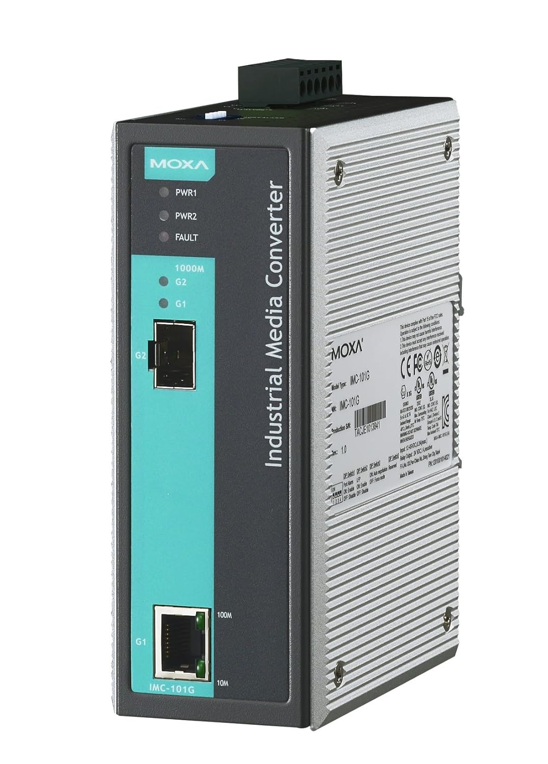
Figure 2: Angled side view of the MOXA IMC-101G Industrial Media Converter. This image highlights the product label with model type, serial number, and various compliance markings.
LED Indicators
The IMC-101G is equipped with several LED indicators to provide real-time status information:
| LED Name | Status | Description |
|---|---|---|
| PWR1 | On | Power input 1 is active. |
| Off | Power input 1 is inactive. | |
| PWR2 | On | Power input 2 is active. |
| Off | Power input 2 is inactive. | |
| FAULT | On | System fault or port break detected. |
| Off | No system fault. | |
| 1000M (G2) | On | SFP port (G2) has a 1000 Mbps link. |
| Blinking | SFP port (G2) is transmitting/receiving data. | |
| G1 (Link/Act) | On | RJ45 port (G1) has an active link. |
| Blinking | RJ45 port (G1) is transmitting/receiving data. | |
| 100M (G1) | On | RJ45 port (G1) has a 100 Mbps link. |
| 10M (G1) | On | RJ45 port (G1) has a 10 Mbps link. |
Setup
DIN-Rail Mounting
The IMC-101G is designed for DIN-rail mounting. To install, attach the DIN-rail kit (if not pre-attached) to the rear of the device using the provided screws. Then, snap the device onto a standard 35mm DIN rail by hooking the top edge of the DIN rail into the slot on the mounting kit and pushing the bottom edge until it clicks into place.
Wiring Requirements
Power Input Wiring
Connect the power inputs to a suitable DC power source using the terminal block. The device supports redundant power inputs (PWR1 and PWR2) for enhanced reliability. Ensure the power supply voltage is within the specified range for the IMC-101G.
Ethernet Port Connection
- Copper Port (G1): Connect your 10/100/1000BaseT(X) Ethernet device (e.g., switch, PC) to the RJ45 port labeled G1 using a standard Ethernet cable.
- Fiber Port (G2): Insert a compatible 1000BaseSFP module into the SFP slot labeled G2. Once the SFP module is securely in place, connect your fiber optic cable to the SFP module. Ensure the fiber type (SX, LX, LHX, ZX) matches the SFP module and your network requirements.
Operating Instructions
Once the IMC-101G is powered on and all network cables are connected, the device will automatically establish a link between the copper and fiber ports. Monitor the LED indicators (PWR1, PWR2, G1, G2, 1000M, 100M, 10M) to confirm proper operation and link status.
Link Fault Pass-Through (LFPT)
The IMC-101G supports Link Fault Pass-Through (LFPT). This feature ensures that if a link fails on one side of the media converter (e.g., the copper Ethernet connection), the link on the other side (the fiber optic connection) is also automatically brought down. This mechanism notifies connected devices of the fault, allowing for quicker network recovery and preventing data loss due to black holes.
Maintenance
Cleaning
Use a soft, dry cloth to clean the exterior of the device. Do not use liquid or aerosol cleaners, as they may damage the components. Ensure the device is powered off before cleaning.
Firmware Updates
Periodically check the official Moxa website for information on available firmware updates. Firmware updates can provide performance enhancements, new features, or bug fixes. Follow the instructions provided by Moxa carefully when performing any firmware update.
Troubleshooting
No Power
- Check all power connections to the terminal block.
- Ensure the power supply is active and providing the correct voltage.
- Verify that the PWR1 and/or PWR2 LEDs are illuminated. If not, check the power source.
No Link
- Copper Port (G1): Verify the Ethernet cable is securely connected to both the IMC-101G and the connected device. Ensure the connected device is powered on and its Ethernet port is active. Check the G1 LED for link status.
- Fiber Port (G2): Ensure the SFP module is correctly inserted and compatible. Verify the fiber optic cable is properly connected and not damaged. Check the G2 and 1000M LEDs for link status. Ensure the fiber type (e.g., single-mode, multi-mode) matches the SFP module and the connected fiber device.
FAULT LED On
A lit FAULT LED indicates a system error or a port break detected by the Link Fault Pass-Through (LFPT) feature. Check all power inputs and network connections. If the issue persists, consult the full product manual on the Moxa website for specific fault codes and advanced troubleshooting steps.
Specifications
The following table lists the key specifications for the MOXA IMC-101G Industrial Media Converter:
| Attribute | Value |
|---|---|
| Brand | Moxa |
| Model | IMC-101G |
| Mounting Type | DIN Rail |
| Number of Pins | 20 |
| Upper Temperature Rating | 60 Degrees Celsius |
| Interface Type | Ethernet |
| Number of Channels | 2 |
| UPC | 747356311533 |
| ASIN | B07CG9VC6D |
Warranty and Support
Warranty Information
This product comes with a standard manufacturer's warranty. Please refer to the warranty card included in the package or visit the official Moxa website for detailed warranty terms and conditions specific to the IMC-101G model.
Technical Support
For technical assistance, troubleshooting, or further inquiries regarding the MOXA IMC-101G, please contact Moxa customer support. You can find contact information and additional resources on their official website: www.moxa.com/support.