1. Introduction
This manual provides essential information for the safe and efficient operation of your Cloudray 150W CO2 Laser Power Supply, Model MYJG-150W MONITOR 110V. This power supply is designed to provide stable and reliable power to 130-150W CO2 laser tubes, suitable for various engraving and cutting applications.
Key features include quick response speed, high performance, and integrated protection mechanisms to prolong the life of your laser tube. It is equipped with an external ammeter for real-time current monitoring and precise adjustments.
2. Safety Information
WARNING: This device operates with high voltage. Improper installation or handling can result in serious injury or death. Always follow safety guidelines and consult a qualified technician if unsure.
- Ensure the power supply is disconnected from the main power source before performing any installation, maintenance, or troubleshooting.
- Do not operate the power supply in wet or damp conditions.
- Ensure proper grounding (FG terminal) to prevent electrical shock.
- Verify all connections are secure and correct before applying power.
- Never touch high-voltage terminals when the unit is powered on.
- Ensure adequate ventilation around the power supply to prevent overheating.
- The power supply includes output open circuit protection. However, avoid operating the laser tube without proper water cooling, as indicated by the water protection signal.

Figure 2.1: Front view of the Cloudray 150W CO2 Laser Power Supply, showing the main casing and ventilation.
3. Product Overview and Components
The Cloudray 150W CO2 Laser Power Supply is designed for robust performance and ease of integration. Familiarize yourself with its key components:
- Main Unit: The primary enclosure housing the power conversion circuitry.
- Input/Output Terminals: Clearly labeled connectors for AC input, laser output, and control signals.
- Cooling Fan: Integrated fan for forced air cooling to maintain optimal operating temperature.
- Test Button: Allows for manual testing of laser output.
- External Ammeter Port: Connection for the included LCD ammeter to monitor current.

Figure 3.1: Detailed view highlighting the product label, connection ports, external ammeter, and cooling fan.
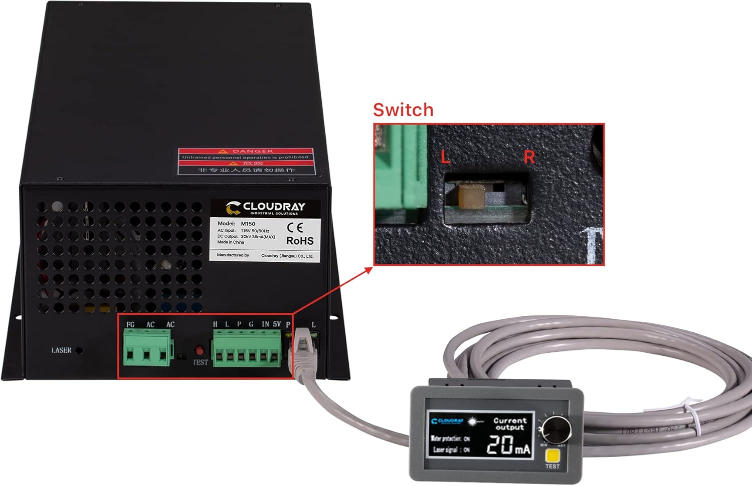
Figure 3.2: The power supply connected to the external ammeter, with an inset showing the internal switch for current adjustment.
4. Setup and Installation
Proper installation is crucial for the performance and longevity of your laser power supply. Follow these steps carefully:
- Mounting: Securely mount the power supply in a well-ventilated area, away from excessive heat, dust, and moisture. Ensure sufficient space for airflow around the cooling fan.
- Power Input (AC115V): Connect the AC input (L and N) to a stable 110V AC power source. Ensure the FG (Frame Ground) terminal is properly connected to earth ground.
- High Voltage Output (LASER): Connect the high voltage output terminal (marked "LASER") to the anode (+) of your CO2 laser tube. Connect the cathode (-) of the laser tube to the return path of your laser system, which typically connects back to the power supply's ground or a dedicated return terminal. Refer to your laser tube's manual for specific wiring.
- Control Signal Connections:
- H/L (Switch Laser Control): Connect for active high or active low laser control signals.
- P (Water Protection): Connect to your water protection sensor. The power supply will stop output if water flow is interrupted.
- G (Signal Ground): Common ground for control signals.
- IN (Input Control Signal 0-5V): For analog power control.
- 5V (Output Power 5V): Provides 5V output for external control circuits.
- Ammeter Connection: Connect the provided external LCD ammeter to the designated port on the power supply. This allows for real-time monitoring of the laser current.

Figure 4.1: Detailed wiring diagram for the power supply connections.

Figure 4.2: Example setup showing the power supply connected to a laser tube.
5. Operating Instructions
Once installed, the power supply is ready for operation. Always ensure your laser system's cooling and safety interlocks are functional before proceeding.
- Power On: Apply AC power to the unit. The internal fan should start, and the external ammeter display will illuminate.
- Current Monitoring: The external LCD ammeter displays the real-time processing current. Monitor this value to ensure it stays within the safe operating range for your laser tube (typically 20-30mA for 150W tubes, consult your laser tube's specifications).
- Current Adjustment: Use the trimmer potentiometer on the external ammeter to fine-tune the output current as needed for different materials or desired engraving/cutting depth.
- TTL Control: The power supply responds to TTL level signals for laser start and stop. Ensure your laser controller is properly configured to send these signals.
- Manual Test: Press the "TEST" button on the power supply or the external ammeter to manually fire the laser for a brief period. Use this for quick checks, ensuring safety precautions are in place.
- Signal Indications: The ammeter display also shows status indications for "Water protection" and "Laser signal".
- "Water protection: ON" indicates the water cooling system is functioning correctly. If "OFF", the laser will not fire.
- "Laser signal: ON" indicates the power supply is receiving a laser firing signal.

Figure 5.1: Ammeter display showing current and status indications.
6. Maintenance
Regular maintenance ensures the longevity and optimal performance of your Cloudray Laser Power Supply.
- Cleaning: Periodically clean the exterior of the power supply, especially the ventilation grilles and fan blades, to prevent dust buildup. Use a soft, dry cloth or compressed air. Ensure the unit is powered off and disconnected before cleaning.
- Ventilation: Ensure the area around the power supply remains clear and unobstructed to allow for proper airflow and efficient cooling.
- Connections: Periodically check all electrical connections for tightness and signs of corrosion. Loose connections can lead to arcing and damage.
- Environmental Conditions: Operate the power supply within the recommended environmental conditions (-30°C to +65°C). Avoid extreme temperatures and humidity.
7. Troubleshooting
This section addresses common issues you might encounter. For problems not listed here, contact Cloudray support.
| Problem | Possible Cause | Solution |
|---|---|---|
| No laser output |
|
|
| Ammeter shows 0mA or erratic readings |
|
|
| Power supply overheating |
|
|
8. Specifications
Technical specifications for the Cloudray 150W CO2 Laser Power Supply (Model MYJG-150W MONITOR 110V):
| Parameter | Value |
|---|---|
| Model | MYJG-150W MONITOR 110V |
| Input Voltage | AC115V |
| AC Frequency | 47 ~ 440Hz |
| Max Output Voltage | 34KV |
| Max Output Current | 38mA |
| Dimensions (L x W x H) | 305 x 161 x 91 mm (14.96 x 7.87 x 5.91 inches) |
| Weight | 3.6 kg (8.6 pounds) |
| Efficiency | 91% |
| MTBF (Mean Time Between Failures) | ≥ 30000 hours |
| Response Speed | ≤ 1ms |
| Voltage Range (High-Level) | ≥ 3V |
| Voltage Range (Low-Level) | ≤ 0.7V |
| Operating Environment Temperature | -30°C ~ +65°C |
| Cooling Method | Forced air cooling (fan cooling) |
| High Temperature Test | Full Load / 60°C / 12 hours |
| Start / Stop Test | 500 times 7 seconds |

Figure 8.1: Visual representation of the technical specifications table.
9. Warranty and Support
For warranty information and technical support, please refer to the official Cloudray website or contact your authorized dealer. Keep your purchase receipt as proof of purchase for any warranty claims.
Cloudray is committed to providing reliable products and customer service. If you encounter any issues or have questions regarding the operation or maintenance of your power supply, please reach out to their support channels.


