1. Introduction
This manual provides essential information for the installation, operation, and maintenance of the Ruckus Wireless ICX 7150 Ethernet Switch. Please read this manual thoroughly before operating the device to ensure proper usage and to prevent damage.
2. Safety Information
- Ensure the power supply voltage matches the device's requirements.
- Do not open the device casing; refer all servicing to qualified personnel.
- Avoid placing the switch in areas with high humidity, extreme temperatures, or direct sunlight.
- Ensure proper ventilation to prevent overheating.
- Use only approved power cords and accessories.
3. Package Contents
Verify that all items are present in the package:
- Ruckus Wireless ICX 7150 Ethernet Switch (ICX7150-24-4X10GR-RMT3)
- Power Cord
- Rack Mount Kit (brackets and screws)
- Console Cable (RJ-45 to DB-9)
- Quick Start Guide
4. Physical Overview
The following image illustrates the front panel of the Ruckus Wireless ICX 7150 Ethernet Switch, highlighting its various ports and indicators.
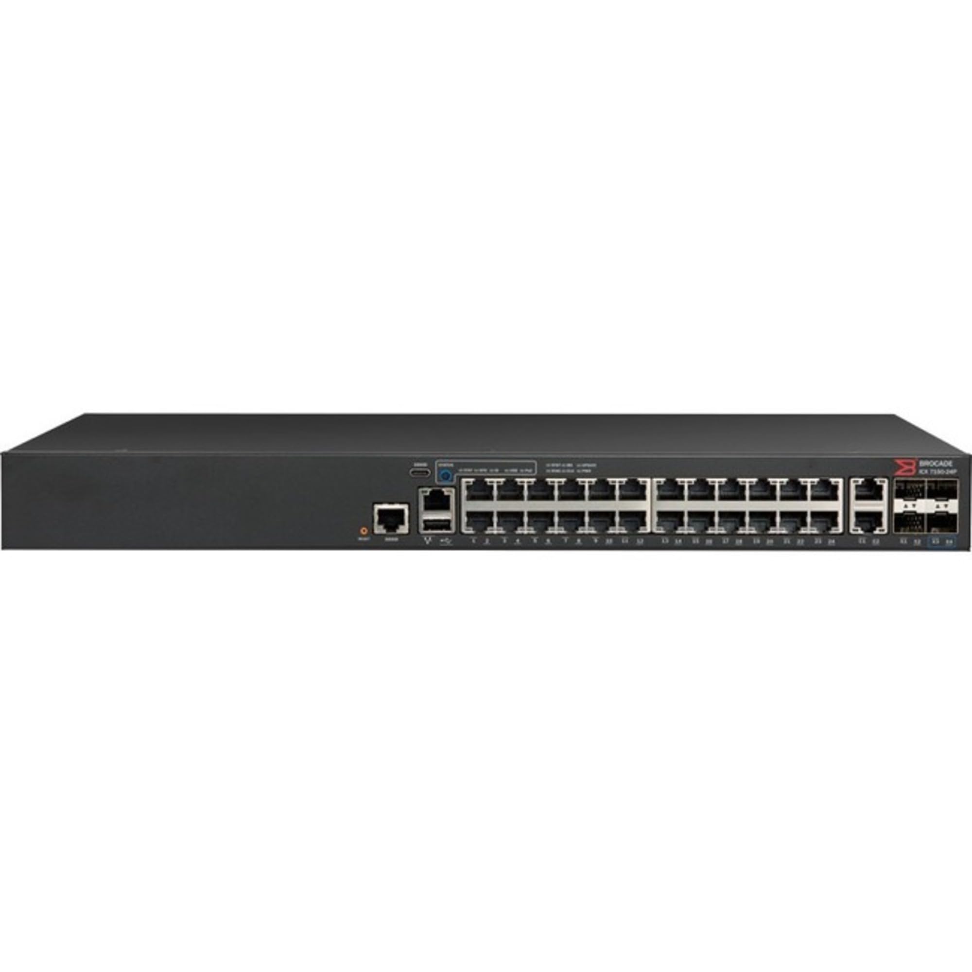
Figure 1: Front Panel of ICX 7150 Ethernet Switch. This image displays the front view of the Ruckus Wireless ICX 7150-24-4X10GR-RMT3 switch. From left to right, it features a USB-C console port, a standard RJ-45 console port, a USB-A port, and 24 Gigabit Ethernet ports (numbered 1-24). On the far right, there are four 10 Gigabit SFP+ uplink ports (labeled 1-4). Various LED indicators for system status and port activity are also visible above the ports.
Front Panel Components:
- 24 x 10/100/1000Base-T Ethernet Ports: RJ-45 connectors for standard network connections.
- 4 x 10 Gigabit SFP+ Uplink Ports: For high-speed fiber or copper connections to other network devices.
- Console Port (RJ-45 and USB-C): For local management and initial configuration.
- USB-A Port: For firmware upgrades or configuration backup/restore.
- LED Indicators: Provide status information for power, system, and individual port activity.
5. Setup
5.1 Rack Mounting
- Attach the rack-mount brackets to the sides of the switch using the provided screws.
- Secure the switch into a standard 19-inch equipment rack using appropriate rack screws.
- Ensure adequate space for airflow around the device.
5.2 Connecting Power
- Connect the power cord to the AC power inlet on the rear panel of the switch.
- Plug the other end of the power cord into a grounded electrical outlet.
- Verify that the power LED on the front panel illuminates.
5.3 Connecting Network Cables
- Connect Ethernet cables from your network devices (computers, servers, access points) to the 10/100/1000Base-T ports on the switch.
- For uplink connections to other switches or routers, use SFP+ transceivers and fiber optic cables (or DAC cables) in the 10 Gigabit SFP+ ports.
- Observe the port status LEDs for link and activity indications.
5.4 Initial Configuration Access
- Connect a computer to the console port using the provided console cable.
- Configure your terminal emulation software (e.g., PuTTY, Tera Term) with the following settings: 9600 baud, 8 data bits, no parity, 1 stop bit, no flow control.
- Power on the switch and follow the on-screen prompts to perform initial setup, including IP address assignment and basic security settings.
6. Operating
6.1 Powering On/Off
- Power On: Connect the power cord. The switch will automatically power on.
- Power Off: Disconnect the power cord from the electrical outlet. For controlled shutdown, consult the device's command-line interface (CLI) documentation.
6.2 LED Indicators
The front panel LEDs provide visual status of the switch:
- System LED: Indicates overall device status (e.g., green for normal operation, amber for fault).
- Port Link/Activity LEDs: Indicate link status (solid green for link) and data activity (flashing green).
- Refer to the full product documentation for a detailed explanation of all LED states.
6.3 Basic Network Configuration
After initial setup, further configuration can be performed via the CLI or a web-based management interface (if available). Common configurations include:
- VLAN (Virtual Local Area Network) creation and assignment.
- Spanning Tree Protocol (STP) settings.
- Quality of Service (QoS) parameters.
- Security features (e.g., port security, access control lists).
7. Maintenance
7.1 Firmware Updates
Periodically check the Ruckus Wireless support website for the latest firmware versions. Firmware updates can provide new features, performance improvements, and security patches. Follow the instructions provided with the firmware package for a safe update process.
7.2 Cleaning
Ensure the switch is powered off and disconnected from power before cleaning. Use a soft, dry cloth to wipe the exterior. Do not use liquid or aerosol cleaners. Keep ventilation openings clear of dust and debris.
7.3 Environmental Considerations
Maintain the operating environment within the specified temperature and humidity ranges to ensure optimal performance and longevity of the device.
8. Troubleshooting
- No Power: Check power cord connection, power outlet, and power supply. Verify the power LED status.
- No Link on Port: Verify cable connection, cable integrity, and the connected device's status. Check port link LED.
- Network Access Issues: Confirm IP address configuration, VLAN settings, and gateway settings. Check for IP conflicts.
- Device Unresponsive: Attempt to access via console port. If unresponsive, perform a power cycle. As a last resort, consider a factory reset (consult documentation for procedure, as this will erase all configurations).
9. Specifications
| Feature | Description |
|---|---|
| Brand | Ruckus Wireless |
| Model | ICX7150-24-4X10GR-RMT3 |
| Ports | 24 x 10/100/1000Base-T, 4 x 10 Gigabit SFP+ Uplink |
| Manageability | Manageable |
| Item Weight | 8.38 pounds (3800 Grams) |
| ASIN | B07B9RMMPL |
| UPC | 098379121938 |
10. Warranty Information
The Ruckus Wireless ICX 7150 Ethernet Switch typically comes with a limited hardware warranty. For specific warranty terms and conditions, please refer to the warranty card included with your product or visit the official Ruckus Wireless website. Keep your proof of purchase for warranty claims.
11. Technical Support
For technical assistance, product documentation, or software downloads, please visit the Ruckus Wireless support portal or contact their customer service. Have your product model and serial number ready when contacting support.
- Ruckus Wireless Support Website: www.ruckuswireless.com/support (Example link, verify actual URL)