1. Introduction
The MaxProLogic is an FPGA development board designed to facilitate digital design learning and project development. It features the Altera MAX10 FPGA, a powerful chip with 4,000 Logic Elements and 200Kbits of Memory. This board is suitable for various applications, from educational exercises to advanced projects requiring Analog-to-Digital Conversion capabilities.
The MAX10 FPGA includes built-in Flash for configuration and incorporates 8 channels of 12-bit Analog-to-Digital Conversion, enabling diverse project creation. The MaxProLogic is designed for ease of use and cost-effectiveness in digital design.
2. Key Features
- Altera 10M04SA FPGA: Equipped with 4,000 Logic Elements, 20KBytes of SRAM, and on-chip low voltage regulators.
- Integrated Configuration Flash: The MAX10 FPGA includes internal flash memory for configuration storage.
- Analog-to-Digital Converter (ADC): Features an on-chip 12-bit ADC with 8 analog input channels, capable of 1 MSamples/Second.
- Input/Output (I/O): Provides 65 available I/O pins at connectors for extensive interfacing.
- Onboard Indicators: Includes 8 user-configurable green LEDs.
- User Interface: Features a power pushbutton switch and one user-configurable pushbutton switch.
- Sensors: Integrated temperature sensor.
- Power Control: On/Off controller for power management.
3. Board Components and Layout
This section identifies the key components and connectors on the MaxProLogic development board.
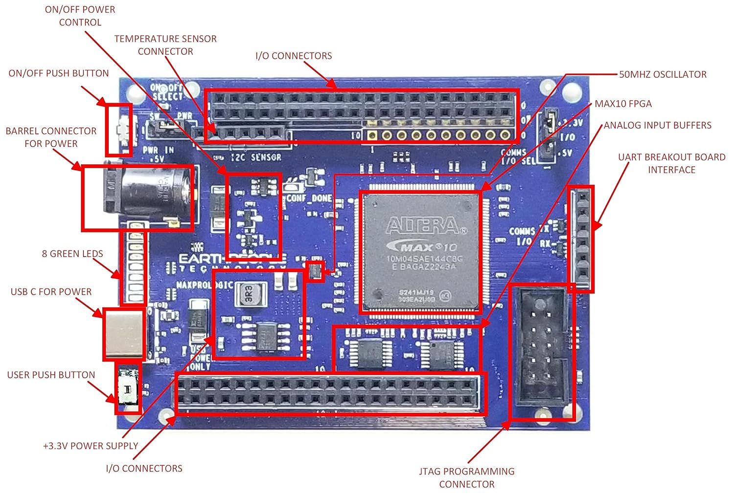
Figure 3.1: Labeled diagram of the MaxProLogic FPGA Development Board. This image highlights the location of the MAX10 FPGA, I/O connectors, power input options (barrel connector, USB-C), on/off switch, pushbuttons, LEDs, temperature sensor, 50MHz oscillator, analog input buffers, UART breakout board interface, and JTAG programming connector.

Figure 3.2: Angled view of the MaxProLogic FPGA Development Board, showing the overall layout and various connectors from a perspective angle.
4. Setup Instructions
4.1 Powering the Board
The MaxProLogic board can be powered via two methods:
- USB-C Port: Connect a standard USB-C cable from your computer or a 5V USB power adapter to the USB-C port labeled 'USB POWER ONLY' on the board.
- Barrel Connector: Connect a 5V DC power supply to the barrel connector labeled 'PWR IN +5V'.
Ensure only one power source is connected at a time to avoid potential damage.
4.2 Connecting for Programming
An external JTAG programmer is required for configuring the Altera MAX10 FPGA. Connect the JTAG programmer to the dedicated JTAG programming connector on the MaxProLogic board. Then, connect the JTAG programmer to your computer via its USB interface.
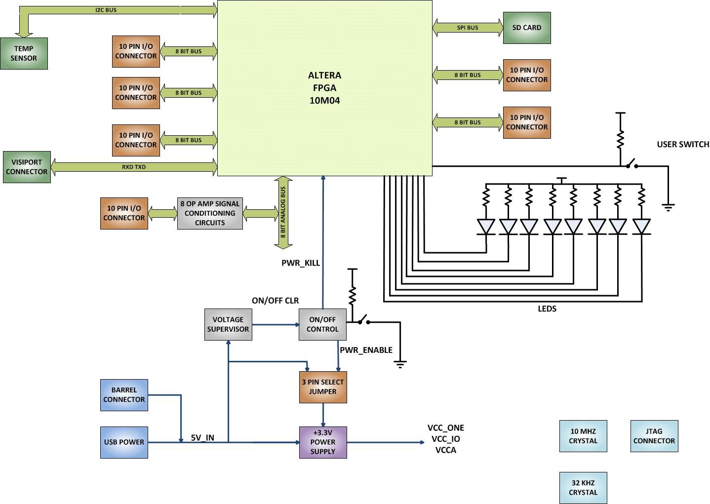
Figure 4.1: Connection diagram illustrating the MaxProLogic board connected to an external JTAG programmer, which is then connected to a computer for programming and development.
4.3 Software Installation
The MaxProLogic leverages the Quartus Prime Lite Software for compilation and synthesis. This software tool is free and provides powerful tools for FPGA development. Additionally, the ModelSim simulation tool is included with Quartus Prime Lite.
- Download and install Quartus Prime Lite Edition from the Intel FPGA website.
- Ensure that the necessary device support for MAX10 FPGAs is installed during the Quartus installation process.
- Install the drivers for your JTAG programmer as per the manufacturer's instructions.
5. Operating Instructions
This section outlines the general workflow for developing and programming projects on the MaxProLogic board using Quartus Prime Lite.
5.1 Project Creation and Management
To begin a new project:
- Create a New Project: Use the New Project Wizard in Quartus Prime to set up your project.
- Organize User Files: Establish a clear folder structure for your project files (e.g., source code, constraints, simulation files).
- Add User Files: Include your VHDL or Verilog source files into the project.
- Add MegaFunction IP Files: If using intellectual property (IP) cores, add them to your project.
- Add Synopsys Design Constraints (SDC): Define timing constraints for your design.
5.2 Pin Assignment
Assign the inputs and outputs of your design to the physical pins of the MAX10 FPGA on the MaxProLogic board. Refer to the board's schematic (available on the Earth People Technology website) for accurate pin mappings.
5.3 Compilation and Synthesis
After defining your design and assigning pins:
- Compile the Design: Initiate the compilation process in Quartus Prime. This step includes synthesis, fitting, and assembly.
- Synthesize the Project: The synthesis process translates your HDL code into a gate-level netlist.
5.4 Programming the FPGA
Once compilation is successful, program the design onto the MAX10 FPGA:
- Ensure the JTAG programmer is correctly connected to the board and your computer.
- Open the Programmer tool within Quartus Prime.
- Select your JTAG programmer and the generated programming file (.sof or .pof).
- Initiate the programming process to load your design onto the MAX10 FPGA.
5.5 Onboard Peripherals
The MaxProLogic board includes several onboard peripherals for testing and interaction:
- LEDs: The 8 green LEDs can be controlled by your FPGA design for visual feedback.
- Pushbutton Switches: One power switch and one user-configurable switch are available for input.
- Temperature Sensor: Interface with the onboard temperature sensor via the FPGA for environmental monitoring.
- Analog Inputs: Utilize the 8 analog input channels for connecting external analog signals to the FPGA's ADC.

Figure 5.1: Block diagram illustrating the internal connections and components of the MaxProLogic board, including the Altera FPGA, I/O connectors, power supply, LEDs, user switch, temperature sensor, and analog signal conditioning circuits.
6. Specifications
| Feature | Specification |
|---|---|
| FPGA Model | Altera 10M04SA (MAX10 family) |
| Logic Elements | 4,000 |
| Memory (SRAM) | 20 KBytes |
| Analog Input Channels | 8 channels, 12-bit, 1 MSamples/Second |
| Available I/O's | 65 at connectors |
| Onboard LEDs | 8 Green, user-configurable |
| Pushbutton Switches | 1 Power, 1 User-configurable |
| Sensors | Temperature Sensor |
| Power Input | 5V DC via USB-C or Barrel Connector |
| Connectivity Technology | Ethernet (implied by product category, but not directly on board) |
| Product Dimensions | 3.2 x 2.4 x 0.5 inches |
| Item Model Number | EPT-10M04-AF-S2 |
7. Troubleshooting
This section provides guidance for common issues encountered during the use of the MaxProLogic board.
7.1 Board Not Powering On
- Check Power Source: Ensure the 5V power supply (USB-C or barrel connector) is correctly connected and providing power.
- Verify Power Switch: Confirm the onboard power switch is in the 'ON' position.
- Single Power Input: Ensure only one power source is connected at a time.
7.2 FPGA Not Configuring/Programming
- JTAG Connection: Verify that the external JTAG programmer is securely connected to both the MaxProLogic board and the computer.
- JTAG Driver: Confirm that the correct drivers for your JTAG programmer are installed and functioning.
- Quartus Programmer Settings: In Quartus Prime Programmer, ensure the correct JTAG chain is detected and the programming file (.sof or .pof) is selected.
- Power to Board: The board must be powered on for programming to succeed.
7.3 Onboard Switches/LEDs Not Responding
- Pin Assignments: Double-check your pin assignments in Quartus Prime to ensure the switches and LEDs are mapped to the correct FPGA pins.
- Logic Design: Verify that your FPGA logic design correctly reads inputs from the switches and drives outputs to the LEDs.
- Power: Ensure the board is adequately powered.
7.4 Regulator Overheating (when using external supply)
- Input Voltage: Ensure the external power supply voltage is exactly 5V. Higher voltages can cause the onboard regulators to dissipate more heat.
- Current Draw: If your design draws significant current, consider using a power supply capable of delivering sufficient current without voltage drop.
8. Maintenance
Proper handling and storage will ensure the longevity of your MaxProLogic development board.
- Static Discharge: Always handle the board in an anti-static environment to prevent damage from electrostatic discharge (ESD).
- Cleanliness: Keep the board free from dust and debris. Use compressed air or a soft brush for cleaning.
- Storage: Store the board in its original packaging or an anti-static bag when not in use, in a dry environment.
- Power Off: Always disconnect power before making any physical connections or disconnections to the board.
9. Support and Resources
For additional support, detailed schematics, data sheets, and project files, please visit the official Earth People Technology website:
The website provides comprehensive resources to assist users from unpacking the board to creating complex projects using the Quartus Software Tool.
10. Warranty Information
Specific warranty details for the MaxProLogic FPGA Development Board are not provided in this manual. Please refer to the Earth People Technology website or contact customer support for current warranty terms and conditions.