
1. Important Safety Information
Please read all instructions carefully before installing and operating this thermostat. Failure to follow these instructions could result in property damage, personal injury, or death. Installation should be performed by a qualified electrician in accordance with local electrical codes.
- Always disconnect power at the main circuit breaker before installing or servicing the thermostat.
- This thermostat is designed for 120VAC / 240VAC, 50/60Hz systems only. Ensure your system voltage matches.
- The built-in Ground Fault Circuit Interrupter (GFCI) is a critical safety feature. Test it regularly as described in the operating section.
- Do not operate the thermostat if the GFCI is tripping continuously, as this indicates an electrical leakage.
2. Product Overview
The Senphus Radiant Underfloor Heating Thermostat is an intelligent device designed to control electric floor warming systems, heating cables, electrothermal films, and similar heating elements. It features a dual voltage design (120V/240V), a programmable 7-day schedule, and a built-in Class A (5mA trip level) GFCI for enhanced safety. The thermostat includes both air and floor sensors to maintain precise temperature control.

Figure 2.1: Front and back view of the Senphus Radiant Underfloor Heating Thermostat. The front features an LCD display and touch buttons, while the back shows the wiring terminals and mounting plate.
Key Features:
- Dual Voltage Compatibility: 120VAC / 240VAC, 50/60Hz.
- Maximum Load: 15A (1800W at 120V, 3600W at 240V).
- Integrated Class A GFCI (5mA trip level) with test function.
- Includes both floor and ambient air temperature sensors.
- Large LCD digital display with backlight for clear readability.
- 7-day programmable schedule for energy efficiency.
- ON/STANDBY switch for seasonal shutdown.
- ETL Listed, complying with CAN/CSA-E60730-1 and CAN/CSA-E60730-2-9 standards.
3. Installation
3.1 Mounting Requirements
The thermostat should be installed inside a standard single-gang electrical wall box with a minimum depth of 30mm (approximately 1.2 inches). Ensure adequate space for wiring connections.

Figure 3.1: Illustration of the thermostat's mounting plate, showing the universal base installation hole distance of 3-1/4 inches (83mm) and the requirement for a single-gang electrical wall box at least 30mm deep.
3.2 Wiring Instructions
All wiring must comply with local electrical codes. Refer to the wiring diagram on the back of the thermostat and the images below for correct connections. Ensure power is OFF before proceeding.
- Connect the Line 1 (L) and Line 2 (N) wires from your power supply to the corresponding terminals on the thermostat. The thermostat supports both 120V and 240V systems.
- Connect the Load 1 and Load 2 wires from your heating element to the designated Load terminals on the thermostat.
- Connect the floor sensor wires to the "Sensor" terminals. The floor sensor can be installed either in the floor or outside the house, depending on your heating system design.
- Ensure all connections are secure.

Figure 3.2: Detailed view of the thermostat's wiring terminals, indicating connections for Line 1 (L), Line 2 (N), Load 1, Load 2, and the floor sensor. This image also highlights the dual voltage self-adaptation design.

Figure 3.3: Example of wires connected to the thermostat's terminals, demonstrating proper wiring practice before mounting.
3.3 Sensor Placement
The thermostat includes an internal air sensor and an external floor sensor. The internal air sensor is located at the top of the thermostat for accurate ambient temperature readings. Ensure the thermostat is not placed in direct sunlight or near other heat sources that could affect its readings.

Figure 3.4: Close-up view showing the location of the air sensor inside the thermostat, positioned at the top for optimal heat dissipation and temperature sensing.
4. Operating Instructions
4.1 Display and Buttons
The thermostat features a large LCD display with backlight and touch-sensitive buttons for easy operation. The display shows current temperature, set temperature, time, day of the week, and operating mode.

Figure 4.1: Front view of the thermostat highlighting the touch buttons and the LCD display. The icons are designed for intuitive understanding, and the protective circuit board prevents moisture and dust entry.
4.2 Initial Power-Up and Settings
Upon initial power-up, the thermostat will display default settings. You will need to set the current time and day of the week. Consult the detailed programming instructions provided in the original package for specific steps on navigating menus and adjusting settings.
4.3 7-Day Programmable Schedule
The thermostat allows for a 7-day programmable schedule, enabling you to set different temperature profiles for various times of the day and days of the week. This feature helps optimize comfort and energy consumption. Refer to the full instruction manual for detailed programming steps.
4.4 GFCI Test Function
The built-in GFCI must be tested monthly to ensure proper operation. To perform a GFCI test:
- Ensure the heating cable is energized and the thermostat is in an ON state.
- Press the "GFCI Test" button (usually labeled "Test" or with a GFCI icon) on the thermostat.
- The GFCI icon should appear on the display, and the heating output should stop. The GFCI indicator light will illuminate.
- To reset, press the "Reset" button (or the same GFCI Test button again). The GFCI icon should disappear, and heating should resume.
- If the GFCI does not trip or reset correctly, discontinue use and consult a qualified electrician.
5. Maintenance
- Cleaning: Gently wipe the thermostat's screen and casing with a soft, damp cloth. Do not use abrasive cleaners or solvents.
- GFCI Testing: Perform the GFCI test monthly to ensure continued safety.
- Seasonal Shutdown: Use the ON/STANDBY switch to turn off the heating system at the end of the heating season to save energy.
6. Troubleshooting
| Problem | Possible Cause | Solution |
|---|---|---|
| GFCI trips frequently. | Electrical leakage detected (greater than 5mA). | Immediately shut down main power. Recheck all wiring connections for proper insulation and secure fit. If the issue persists, consult a qualified electrician to inspect the heating system for faults. |
| Thermostat display is blank. | No power supply or loose connection. | Check the circuit breaker. Ensure all wiring connections to the thermostat are secure. |
| Incorrect temperature reading. | Sensor issue or improper placement. | Verify the floor sensor is correctly installed. Ensure the thermostat's air sensor is not obstructed or exposed to drafts/direct heat. |
| Heating system not responding to settings. | Incorrect programming or system in STANDBY mode. | Check the thermostat's operating mode and programmed schedule. Ensure the ON/STANDBY switch is in the ON position. |
7. Specifications
| Feature | Detail |
|---|---|
| Model Number | 43237-2 |
| Brand | Senphus |
| Voltage | 120V / 240V AC, 50/60Hz |
| Maximum Current | 15A |
| Maximum Power Wattage | 1800W (120V) / 3600W (240V) |
| GFCI Trip Level | Class A - 5mA |
| Display Type | LCD with Backlight |
| Control Type | Button Control |
| Sensors Included | Built-in Air Sensor, External Floor Sensor |
| Mounting Type | Wall Mount (Single-gang electrical box) |
| Material | Anti-flammable PC + ABS |
| Item Weight | 0.43 Kilograms |
| Certifications | cETL Listed (CAN/CSA-E60730-1, CAN/CSA-E60730-2-9, CAN/CSA-C22.2 No. 144.1) |
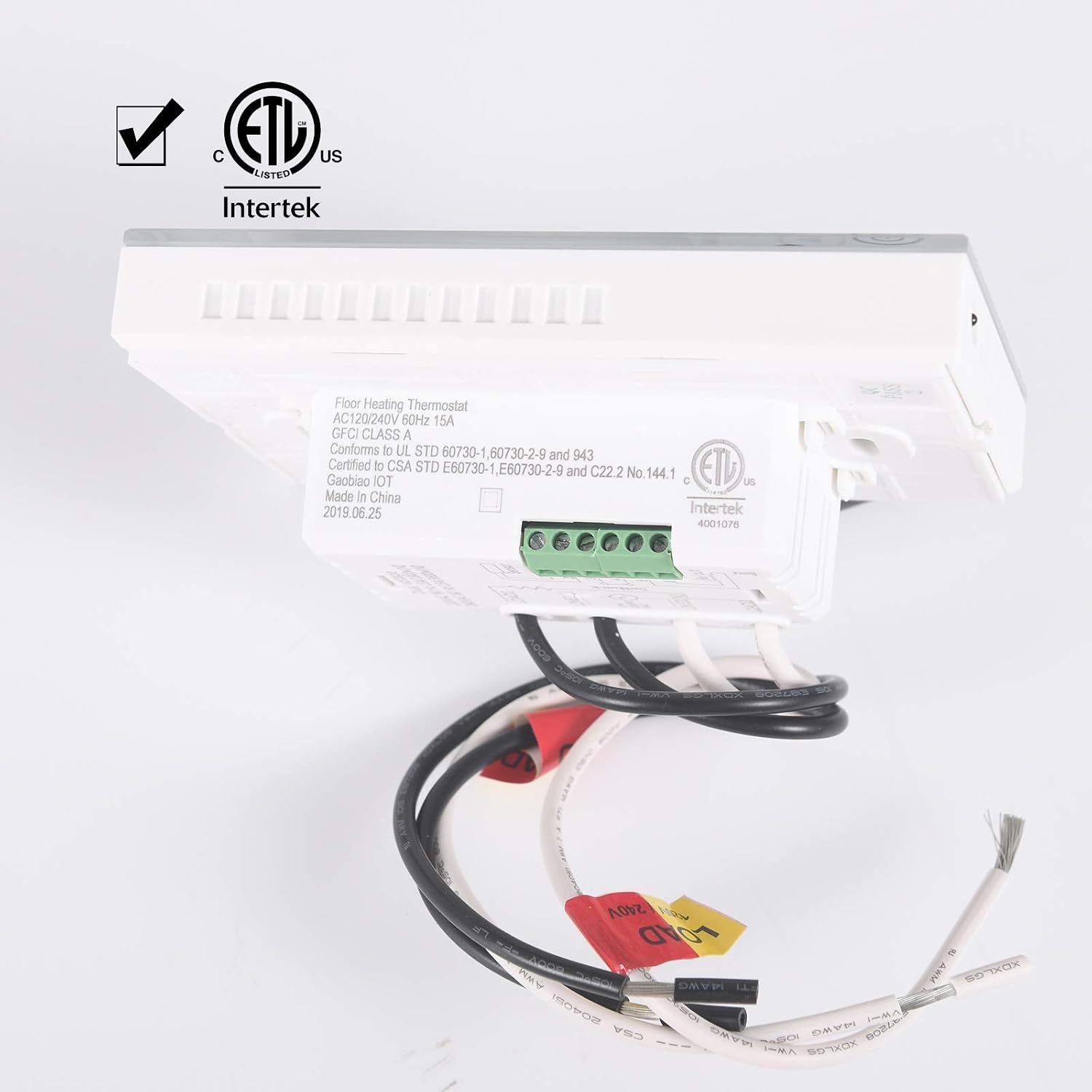
Figure 7.1: The cETL Listed mark, indicating compliance with North American safety standards for electrical controls.
8. Warranty and Support
For warranty information and technical support, please refer to the documentation included with your product package or contact Senphus customer service directly. Keep your purchase receipt as proof of purchase.
The package includes:
- Thermostat with built-in GFCI
- Floor sensor line (14.7 ft)
- 2 screws for the electrical wall box
- 4 screw terminals
- Installation instructions (this document provides a summary; refer to the included booklet for full details)

Figure 8.1: Image showing the typical contents of the product package, including the thermostat, floor sensor, mounting screws, and wiring terminals.