1. Introduction
This manual provides essential information for the proper installation, operation, and maintenance of the System Sensor PC2-WL Horn Strobe. This device is designed for use with fire alarm panels to provide audible and visual notification during an alarm event. It features a white finish and is suitable for ceiling mounting applications.
The PC2-WL Horn Strobe is UL Listed, FM approved, and CSFM certified, ensuring compliance with relevant safety and performance standards.
2. Safety Information
WARNING: Installation must be performed by qualified personnel in accordance with all national and local electrical codes and standards, including NFPA 72.
- Always disconnect power to the fire alarm control panel before installing, servicing, or removing the device.
- Failure to properly wire the device may result in damage to the unit or the fire alarm control panel.
- Ensure the device is installed in an environment within the specified ambient temperature and humidity limits.
- Do not paint the device, as this may impair its performance and visibility.
- Regular testing of the fire alarm system, including notification appliances, is crucial for proper operation.
3. Installation
3.1 Unpacking and Inspection
Carefully unpack the PC2-WL Horn Strobe and inspect it for any signs of shipping damage. Verify that all components, including the mounting plate, are present. If any damage is found or parts are missing, contact your supplier immediately.
3.2 Mounting Location
The PC2-WL is designed for ceiling mounting. Select a location that provides optimal audibility and visibility within the protected area, adhering to local codes and standards for notification appliance placement.
3.3 Wiring
Connect the device to the fire alarm control panel's notification appliance circuit (NAC) terminals. Ensure correct polarity. The device operates on 12/24V DC. Refer to the fire alarm control panel's documentation for specific wiring diagrams and compatibility.
3.4 Device Assembly and Mounting
- Secure the provided mounting plate to the ceiling junction box using appropriate hardware.
- Connect the wiring from the NAC to the terminals on the horn strobe unit.
- Align the horn strobe unit with the mounting plate and secure it by twisting or snapping it into place, ensuring a firm connection.
- Verify that the unit is securely attached and that all wiring connections are tight.
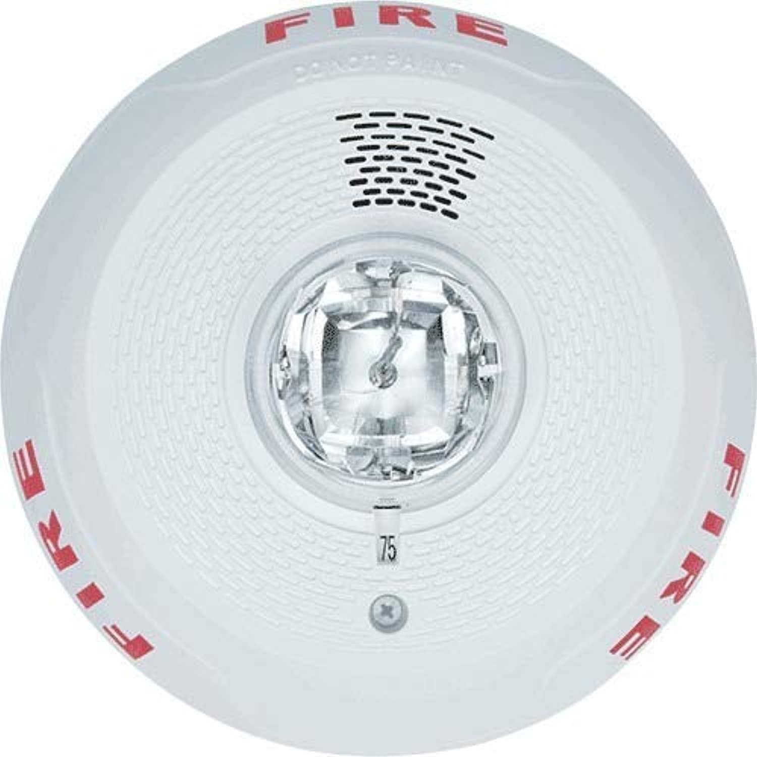
Figure 1: Front view of the System Sensor PC2-WL Horn Strobe. This image displays the device's white circular casing, the central clear strobe light, and the speaker grille. The word "FIRE" is visible in red lettering on the device's surface.
4. Operating Instructions
The System Sensor PC2-WL Horn Strobe operates automatically in conjunction with a compatible fire alarm control panel. When the fire alarm panel detects an alarm condition, it will activate the horn strobe.
- Horn Function: Upon activation, the device will emit an audible alarm signal with a peak output of 90 dBA.
- Strobe Function: Simultaneously, the integrated strobe light will flash at a specified candela rating (15/177 candela), providing a visual alert.
The device remains in standby mode with 0 mA current draw until an alarm condition is detected. During an alarm state, the current draw ranges from 54 to 289 mA, depending on the selected candela setting and voltage.
5. Maintenance
Regular maintenance ensures the continued reliable operation of your PC2-WL Horn Strobe.
- Cleaning: Periodically clean the exterior of the device with a soft, dry cloth to remove dust and debris. Do not use abrasive cleaners or solvents.
- Testing: Conduct functional tests of the horn and strobe as part of your regular fire alarm system testing schedule, as required by local codes and NFPA 72.
- Inspection: Visually inspect the device for any physical damage, discoloration, or obstructions to the horn or strobe.
- Power Cycle: If the device appears to be malfunctioning, ensure power is disconnected from the fire alarm panel, wait a few minutes, and then restore power. If the issue persists, refer to the troubleshooting section.
6. Troubleshooting
| Problem | Possible Cause | Solution |
|---|---|---|
| Horn or Strobe not activating during alarm. |
|
|
| Horn sounds, but strobe does not flash. |
|
|
| Strobe flashes, but horn does not sound. |
|
|
7. Specifications
| Feature | Detail |
|---|---|
| Model Number | PC2-WL |
| Brand | System Sensor |
| Finish Color | White |
| Mounting Type | Ceiling Mounting |
| Peak Output (Horn) | 90 dBA |
| Flash Candela | 15/177 cd |
| Voltage | 12/24V DC |
| Standby Current | 0 uA |
| Alarm State Current | 54 to 289 mA |
| Ambient Temperature Limits | 32 to 120°F (0 to 49°C) |
| Humidity Range | 10 to 93% RH (non-condensing) |
| Dimensions (L x W x H) | 6 27/32 in x 6 27/32 in x 2 1/2 in (approx. 17.4 cm x 17.4 cm x 6.35 cm) |
| Standards | CSFM, FM, UL Listed |
| Material | Plastic |
8. Warranty and Support
System Sensor products are designed for reliability and performance. For specific warranty information, please refer to the warranty statement included with your product packaging or visit the official System Sensor website. For technical support, installation assistance, or to report issues, please contact System Sensor customer service or your authorized distributor.
Manufacturer: System Sensor
Model: PC2-WL
UPC: 783863047435