
Allen-Bradley 700-Hc24a24-1-4
Allen Bradley 700-Hc24a24-1-4 Series C Relay Instruction Manual
Model: 700-Hc24a24-1-4 | Brand: Allen-Bradley
1. Introduction
This manual provides essential information for the safe and effective installation, operation, and maintenance of the Allen Bradley 700-Hc24a24-1-4 Series C Relay. Please read this manual thoroughly before attempting to install or operate the device.
The 700-Hc24a24-1-4 Series C is a general-purpose industrial control relay designed for switching electrical circuits. It operates on 24 Vac at 50/60 Hz.
2. Safety Information
WARNING: Electrical Shock Hazard
- Always disconnect power before installing, servicing, or removing the relay.
- Installation and maintenance should only be performed by qualified personnel.
- Ensure all wiring complies with local and national electrical codes.
- Do not operate the relay if it appears damaged.
Failure to follow these instructions could result in serious injury or death.
3. Product Overview
The Allen Bradley 700-Hc24a24-1-4 Series C Relay is a compact, plug-in type relay. It features a clear housing allowing visual inspection of the contacts and coil. The relay is designed for reliable performance in industrial control applications.

Figure 3.1: Front view of the Allen Bradley 700-Hc24a24-1-4 Series C Relay. This image shows the clear casing, internal components, and the Allen-Bradley branding.
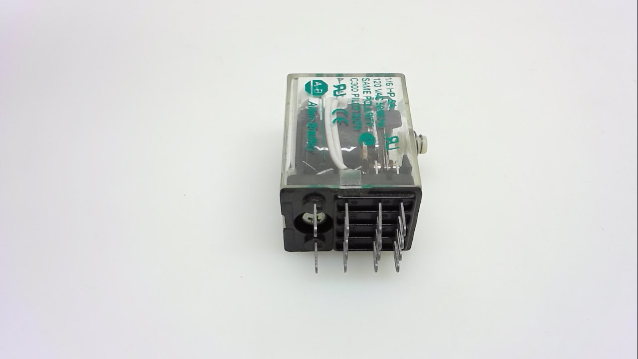
Figure 3.2: Side view of the Allen Bradley 700-Hc24a24-1-4 Series C Relay, highlighting the electrical terminals for connection.

Figure 3.3: Angled top view of the Allen Bradley 700-Hc24a24-1-4 Series C Relay, showing the overall compact design.
4. Installation and Setup
Follow these steps for proper installation:
- Power Disconnection: Ensure all power to the circuit is disconnected before beginning installation.
- Mounting: Insert the relay into a compatible socket or base. Ensure it is seated firmly.
- Wiring: Connect the control voltage (24 Vac, 50/60 Hz) to the coil terminals as indicated on the relay or its associated socket. Connect the load circuit wiring to the appropriate contact terminals (normally open or normally closed) according to your application's schematic. Refer to the relay's pinout diagram (typically found on the relay itself or its datasheet) for correct terminal identification.
- Verification: Double-check all wiring connections for correctness and security.
- Power Restoration: Restore power to the circuit and test the relay's operation.
Note: The relay requires a compatible socket for proper mounting and electrical connection. The socket is typically sold separately.
5. Operation
The 700-Hc24a24-1-4 Series C Relay operates by energizing its coil. When 24 Vac, 50/60 Hz is applied to the coil terminals, an electromagnetic field is generated, which pulls the armature, causing the contacts to change state.
- Energized State: When the coil is energized, normally open (NO) contacts close, and normally closed (NC) contacts open.
- De-energized State: When power is removed from the coil, the contacts return to their original state (NO contacts open, NC contacts close).
The relay acts as an electrical switch, allowing a low-power control signal to control a higher-power load or to provide isolation between circuits.
6. Maintenance
The Allen Bradley 700-Hc24a24-1-4 Series C Relay is designed for minimal maintenance. However, periodic inspection is recommended:
- Visual Inspection: Regularly inspect the relay for any signs of physical damage, discoloration, or loose connections.
- Contact Check: If the relay has a clear cover, visually check the contacts for excessive pitting or carbon buildup, which may indicate wear or overload.
- Cleaning: Keep the relay and its surroundings free from dust and debris. Use a dry, soft cloth for cleaning. Do not use solvents or abrasive cleaners.
- Replacement: If the relay shows signs of wear, damage, or inconsistent operation, it should be replaced immediately by a qualified technician.
7. Troubleshooting
If the relay is not functioning as expected, consider the following common issues:
| Problem | Possible Cause | Solution |
|---|---|---|
| Relay coil does not energize. | No control voltage; incorrect voltage; faulty wiring; damaged coil. | Verify 24 Vac, 50/60 Hz is present at coil terminals; check wiring connections; replace relay if coil is damaged. |
| Contacts do not switch. | Coil not energizing (see above); contacts welded shut; mechanical obstruction. | Address coil issues; replace relay if contacts are damaged or welded. |
| Intermittent operation. | Loose connections; unstable control voltage; worn contacts. | Tighten all connections; ensure stable power supply; replace relay if contacts are worn. |
If troubleshooting steps do not resolve the issue, contact a qualified electrician or Allen-Bradley technical support.
8. Specifications
| Parameter | Value |
|---|---|
| Model Number | 700-Hc24a24-1-4 |
| Series | C |
| Coil Voltage | 24 Vac |
| Frequency | 50/60 Hz |
| Manufacturer | ALLEN BRADLEY |
| ASIN | B079WZNNJS |
| Date First Available | February 19, 2018 |
9. Warranty and Support
For warranty information and technical support, please refer to the official Allen-Bradley website or contact your authorized Allen-Bradley distributor. Specific warranty terms and conditions may vary by region and product. Always provide the model number (700-Hc24a24-1-4) when seeking support.
You can find more information on the official Allen-Bradley website.
Ask a question about this manual
Ask about setup, troubleshooting, compatibility, parts, safety, or missing instructions. Manuals+ will review the question and use this page’s manual context to help answer it.