1. Introduction and Overview
The Ace Instruments AI-DDPG Digital Differential Pressure Gauge is designed for accurate measurement of differential pressure in various critical environments. This device is essential for monitoring air pressure differences in applications such as clean rooms, hospital operating theaters, laminar flow cabinets, and other safety units. It provides precise readings and features communication capabilities for integration into building management systems.

Image 1.1: Illustrative banner highlighting the Digital Differential Pressure Gauge's application in process control environments.
2. Product Features
- Measuring Parameter: Differential Pressure.
- Pressure Range: -250 to 250 Pascals with 4-20mA Output.
- Accuracy: +/- 0.5% of Full Scale.
- Resolution: 1 Pascal.
- Display: Integrated 4 Digit Red LED 7 Segment Display (0.5").
- Maximum Over Pressure: 2 times the rated pressure.
- Sensors: Integrated High Speed Differential Pressure Sensor.
- Communication: RS 485 Modbus RTU Protocol for BMS/SCADA/PLC integration.
- Power Supply: 24 Volts D.C. (Typical).
- Size: Standard 4.5'' (114.3mm) diameter, easily replaceable with magnehelic gauge cutout.
- Depth: 30 mm.
- Weight: 180 Grams.

Image 2.1: Front view of the AI-DDPG Digital Differential Pressure Gauge, showing the LED display and control buttons.

Image 2.2: Illustrative banner showing various measuring ranges available for similar models.
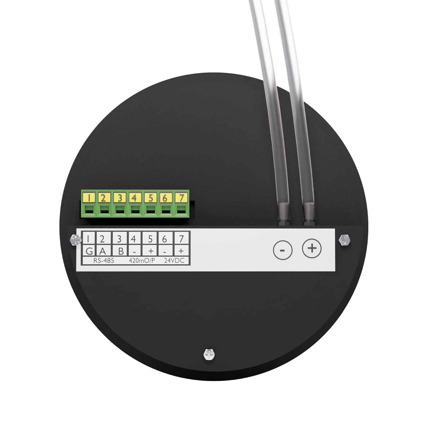
Image 2.3: Back view of the AI-DDPG gauge, showing the terminal block for connections and pressure ports with tubes.

Image 2.4: Illustrative banner detailing the 1/8" port connection size for high and low pressure ports.

Image 2.5: Illustrative banner highlighting RS 485 Modbus communication for BMS/SCADA/PLC integration.

Image 2.6: Illustrative banner explaining positive and negative air pressure readings.

Image 2.7: Illustrative banner showing the unit change function between mm.W.C. and Pascals with a single key press.
3. Specifications
| Specification | Detail |
|---|---|
| Measuring Parameter | Differential Pressure |
| Differential Pressure Range | -250 to 250 Pascals with 4-20mA Output |
| Accuracy | +/- 0.5% of Full Scale |
| Resolution | 1 Pascals |
| Display | Integrated 4 Digit Red LED 7 Segment Display 0.5" |
| Maximum Over Pressure | 2 Times the rated pressure |
| Sensors | Integrated High Speed Differential Pressure Sensor |
| Communication | RS 485 Modbus RTU Protocol |
| Power Supply | 24 Volts D.C. Typical |
| Size (Diameter) | Standard 4.5'' (114.3mm) |
| Depth | 30 mm |
| Weight | 180 Grams (Gauge only) / 300 Grams (Item Weight) |
| Material | Alloy Steel |
| Product Dimensions (L x W x H) | 3.94 x 3.15 x 4.72 inches |
4. Package Contents
Upon unpacking, please verify that all items listed below are present and in good condition:
- 1 Unit of Digital Differential Pressure Gauge (AI-DDPG)
- Silicon Tube for pressure connections
- Power Adapter (24V DC)
- Instruction Manual (this document)
- Factory Calibration Certificate
- Wall Mounting Box

Image 4.1: The AI-DDPG gauge shown with its included power adapter.

Image 4.2: Close-up view of the power adapter's specifications label.

Image 4.3: The wall mounting box provided for installation.
5. Setup and Installation
- Mounting: The AI-DDPG gauge is designed for modular wall fitment and can be easily installed using the provided wall mounting box. It fits standard 4.5'' cutouts, similar to magnehelic gauges.
- Power Connection: Connect the provided 24V D.C. power adapter to the gauge's power input terminals (marked '+' and '-' for 24VDC on the back panel). Ensure correct polarity.
- Pressure Tube Connection: Attach the silicon tubes to the high pressure (+) and low pressure (-) ports located on the back of the gauge. Ensure a secure connection to prevent leaks.
- RS 485 Communication (Optional): For BMS/SCADA/PLC integration, connect the RS 485 communication lines (G, A, B) to the corresponding terminals on the back of the gauge.
- 4-20mA Output (Optional): If utilizing the 4-20mA output, connect the output lines to the designated terminals (4-20mA O/P) on the back panel.

Image 5.1: The AI-DDPG gauge installed on a wall, demonstrating its modular fitment.
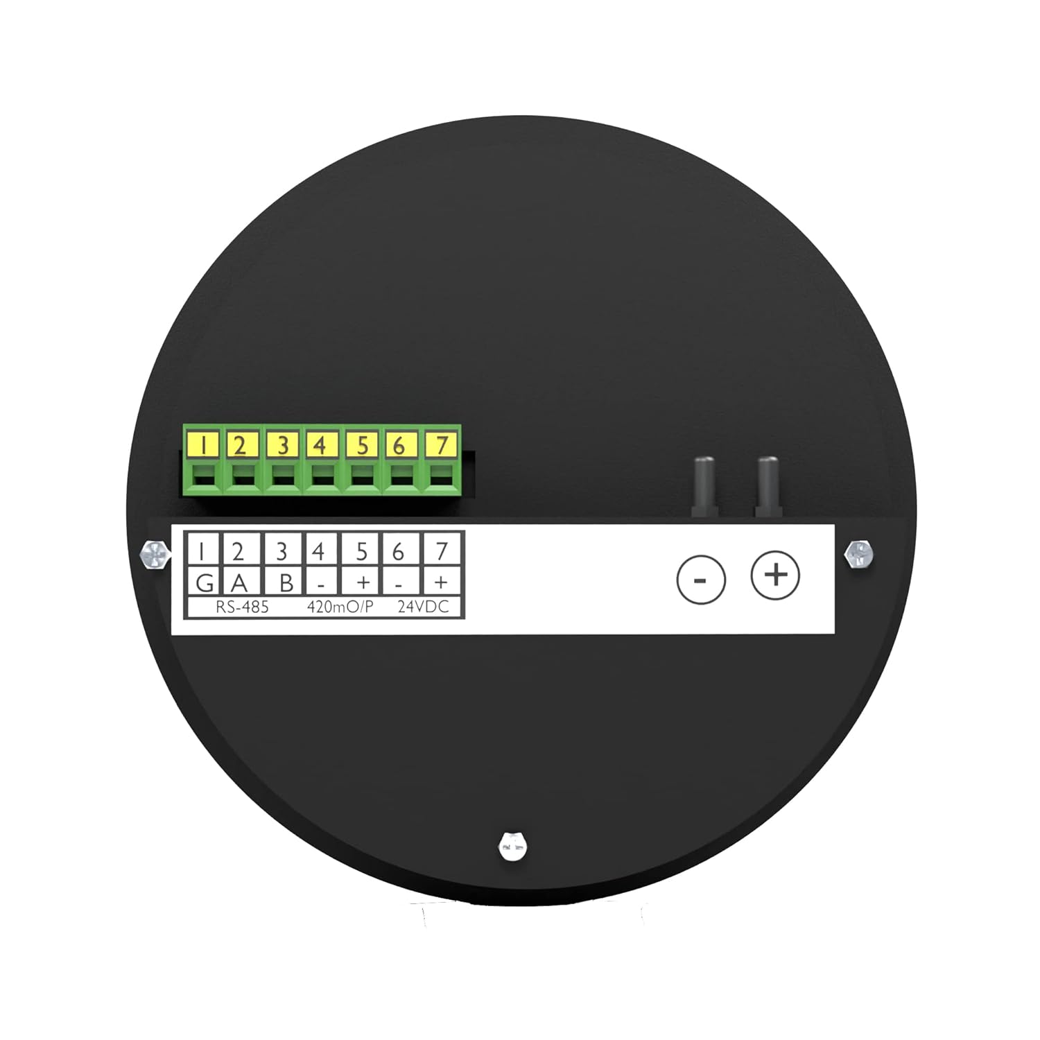
Image 5.2: Detailed back view of the AI-DDPG gauge, illustrating the RS-485, 4-20mA output, and 24VDC power input terminals.

Image 5.3: Illustrative banner emphasizing the 30 mm depth for cleanroom modular wall fitment.
6. Operation
Once the gauge is properly installed and powered, it will display the differential pressure reading on its 4-digit LED display. The unit of measurement (Pascals or mm.W.C.) will be indicated by illuminated LEDs next to the display.
6.1. Unit Selection
To switch between Pascals and mm.W.C., press the 'UNIT/ACK' button on the front panel. The corresponding LED indicator will illuminate to show the currently selected unit.
6.2. Alarm Indicators
The gauge features 'LO' and 'HI' indicators for low and high alarm conditions, respectively. These will illuminate if the measured differential pressure falls outside the configured acceptable range. The 'COM' indicator signifies communication status.
6.3. Programming
The 'PROG' button and arrow keys (up/down) are used for accessing and adjusting various settings and alarm thresholds. Refer to the detailed programming guide (if provided separately) for advanced configuration.
7. Maintenance
- Cleaning: Clean the exterior of the gauge with a soft, dry cloth. Do not use abrasive cleaners or solvents.
- Calibration: Regular calibration is recommended to ensure continued accuracy. Refer to the calibration certificate for details on the recommended calibration interval.
- Tube Inspection: Periodically inspect the silicon pressure tubes for any signs of wear, kinks, or leaks. Replace damaged tubes immediately to maintain measurement integrity.
8. Troubleshooting
If you encounter issues with your AI-DDPG Digital Differential Pressure Gauge, consider the following:
- No Display: Check the power adapter connection and ensure the power supply is active (24V DC).
- Incorrect Readings: Verify that the pressure tubes are correctly connected to the high and low pressure ports and are free from obstructions or leaks. Ensure the gauge is properly calibrated.
- Communication Issues: Check the RS 485 wiring for correct connections (G, A, B) and ensure the communication protocol settings match those of the connected BMS/SCADA/PLC system.
- Alarm Triggered: Investigate the environmental conditions to determine if the differential pressure is genuinely outside the set thresholds. If not, check alarm settings.
For persistent issues, contact Ace Instruments customer support.
9. Warranty and Support
The AI-DDPG Digital Differential Pressure Gauge comes with a factory calibration certificate. For specific warranty terms and conditions, please refer to the documentation provided at the time of purchase or contact Ace Instruments directly. Technical support is available for assistance with installation, operation, and troubleshooting.
Manufacturer: Ace Instruments